Group
21
Reconditioning
engine
Jnstalling
parts
o
25,0
68
KlO
Set
pump
and
tighten
camshaft
rear
sprocket
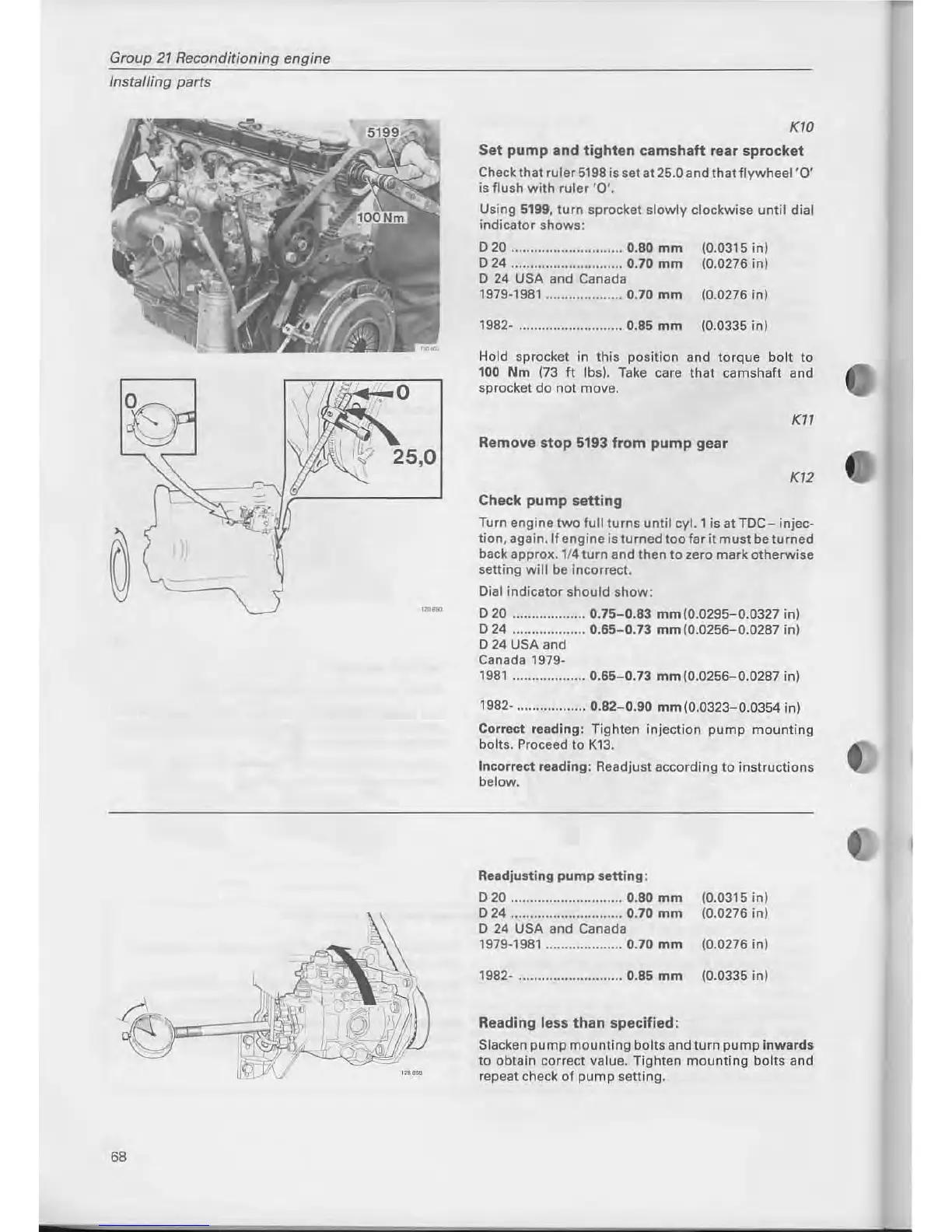
Check that ruler5198 is set at 25.0 and
thatflywheel'O'
is
flush
with
ruler
'O'.
Using 5199,
turn
sprocket
slowly
clockwise
until
dial
indicator
shows:
D20
............................. 0.80
mm
D24
............................. 0.70
mm
D 24 USA and Canada
1979·1981
.................... 0.70
mm
1982· ........................... 0.85
mm
(0.0315 in)
(0.0276 in)
(0.0276 in)
(0.0335 in)
Hold sprocket in
this
position
and
torque
bol t
to
100
Nm
(73 ft Ibs). Take care
that
camshaft
and
sprocket
do
not
move.
KI1
Remove
stop
5193 from
pump
gear
K12
Check
pump
setting
Turn
engine
two
full
turns
until
cyl. 1 is at
TDC-
injec·
tion,
again.lf
engine
is
turned
too
far
it
must
be
turned
back approx. 1/4
turn
and then
to
zero
mark
otherwise
setting
will
be incorrect.
Dial
indicator
should
show:
D
20
...................
0.75-0.83
mm
(0.0295-0.0327
in)
D
24
...................
0.65-0.73
mm
(0.0256-0.0287
in)
D
24
USA and
Canada 1979·
1981
...................
0.65-0.73
mm
(0.0256-0.0287 in)
1982· ..................
0.82-0.90
mm
(0.0323-0.0354
in)
Conect
reading: Tighten injection
pump
mount
ing
bolts. Proceed
to
K13.
Inconect
reading: Readjust according
to
instructions
below.
Readjusting
pump
setting:
020
............................. 0.80
mm
024
............................. 0.70
mm
O
24
USA and Canada
1979·1981
.................... 0.70
mm
1982· ........................... 0.85
mm
Reading
less
than
specified:
(0.0315
in)
(0.0276
in)
(0.0276
in)
(0.0335 in)
Slacken
pump
mounting
bolts
and
turn
pump
inwards
to
obtain
conect
value. Tighten
mounting
bolts
and
repeat check
of
pump
setting.



 To Next Page