Do you have a question about the Volvo D9 and is the answer not in the manual?
OEM designed control systems must apply SAE J1939 standards with additional Volvo Penta proprietary messages.
List of abbreviations used in the document, such as PGN, SPN, FMI, etc.
Details the CAN bus interface used for controlling Volvo Penta marine engines via SAE J1939.
Describes the electrical interface, detailing Connector A and Connector B pin assignments.
Details the 2-pin Deutsch connector for connecting a secondary battery.
Explains the external stop interface, its function, and configuration for different engine models.
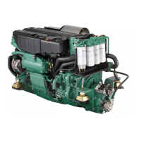
Illustrates the location of connectors for the D9 engine, including main connectors and optional interfaces.
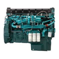
Shows the D13 engine connectors and their corresponding functions and interfaces.
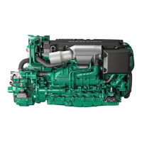
Provides a visual guide to the D16 engine connectors and associated interfaces.
Details the requirements for BB1 CAN bus termination to prevent signal reflection interference.
Lists the source addresses used for PEA2 electrical architecture in hexadecimal and decimal formats.
Explains the procedure for powering up the EMS, including ignition connection and power module activation.
Describes the conditions and signals for initiating an engine start request via CAN or external interface.
Outlines the two methods for requesting engine stop: via CAN message or external stop interface.
Details the EMS power-down sequence, including ignition off logic and self-hold function for data storage.
Explains engine speed control methods using the VP70 CAN message and TSC1 speed control.
Describes specific engine speed control for Genset applications, including synchronization and load sharing.
Explains the 'Idle speed select' function for variable speed and Genset applications.
Details the TSC1 message for requesting speed/torque and limiting engine speed/torque during gear shifts.
Explains governor modes, including 'Engine speed mode' and 'Torque mode' for load sharing.
Describes the 'Engine restored operation' signal for handling critical situations without power loss.
Details J1939 messages, PGNs, SPNs, and signal names for EMS communication.
Defines VP70 messages, signal names, start positions, lengths, and their meanings.
Details the Accelerator pedal position signal, its range, factor, and status codes.
Describes VP71 messages, including running indication, buzzer, and engine power down acknowledgment.
Explains supported Power Module diagnosis, transmitted messages, and diagnostic protocols.
Lists J1587 fault codes, PSID, FMI, and the conditions under which they are active.
| Engine Type | Diesel |
|---|---|
| Cylinders | 6 |
| Displacement | 9.4 liters |
| Torque | 1050-1700 Nm depending on specific model |
| Configuration | Inline |
| Aspiration | Turbocharged |
| Cooling System | Liquid-cooled |