Incorrectly wiring or accidental contact between any wires other than the data ones can
lead to irreversible damage that is not covered by the warranty.
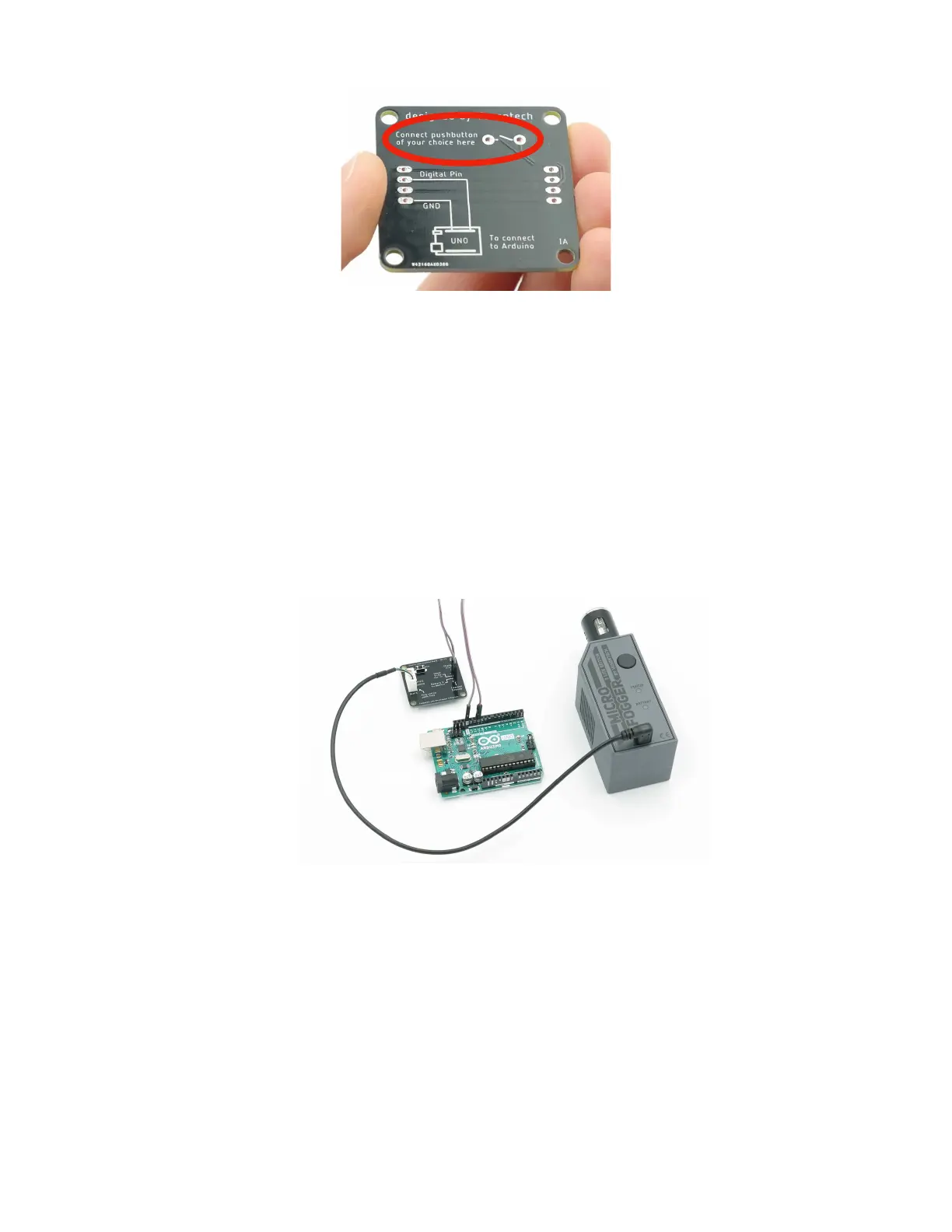
Wired digital control
Similarly, the MicroFogger can also be controlled using a common microcontroller such
as an Arduino. In order to do so, you’ll need to connect the black GND pin of the
breakout board to the ground pin of the microcontroller. You’ll then be able to send a
HIGH or LOW signal to the input pin in order to turn the MicroFogger on or off. The
signal voltage can range from 3V to 5V. You will need to turn the control cable setting
ON in order to allow the cable to work.
External Power
The MicroFogger 5 Pro can be configured to operate while charging so it is possible to
power it off of a USB battery bank or any other other 5V power supply. If using a battery
bank, you can connect it using the included micro USB cable. If a USB port is
inaccessible, our control cable breakout board can be used. Simply connect the positive
terminal of a 5V power supply to the charging pin on the breakout board and the black
wire to the ground pin. This will also allow you to use wired control while keeping the
MicroFogger on charge as long as you have turned off the charge lock setting in the
advanced menu.