3
Connector J3 provides connection for Ethernet ports 1 and 3.
Pin* Signal Pin* Signal Pin* Signal Pin* Signal
1 Port 1 Bidirectional Pair B+ 6 Port 1 Bidirectional Pair A- 11 Port 3 Bidirectional Pair B+ 16 Port 3 Bidirectional Pair A-
2 Port 1 Bidirectional Pair A+ 7 Port 1 Bidirectional Pair B- 12 Port 3 Bidirectional Pair A+ 17 Port 3 Bidirectional Pair B-
3 Port 1 A/B Inner Shield 8 Port 1 C/D Inner Shield 13 Port 3 A/B Inner Shield 18 Port 3 C/D Inner Shield
4 Port 1 Bidirectional Pair D+ 9 Port 1 Bidirectional Pair C- 14 Port 3 Bidirectional Pair D+ 19 Port 3 Bidirectional Pair C-
5 Port 1 Bidirectional Pair C+ 10 Port 1 Bidirectional Pair D- 15 Port 3 Bidirectional Pair C+ 20 Port 3 Bidirectional Pair D-
* Use Deutsch shell DMC-MD 20C, insert & contacts DMC-M 20-22SN, backshell 787-8055-13M or equivalent for mating connector.
Indicator Function
POWER Indicator Lit solid green to indicate powered up and enabled for operation. Flashes to indicate powered up, but operation is
disabled (standby mode). The internal unmanaged Ethernet switch continues to function in standby mode.
RF ENABLE Indicator Lit solid green to indicate RF output is enabled.
WLAN Indicators Flash green to indicate RF data transfers are occurring on the applicable radio card.
LAN Indicators Flash green to indicate applicable LAN data transfers are occurring.
Lit solid green to indicate that a link is established on applicable wired LAN ports, but no data transfers are occurring.
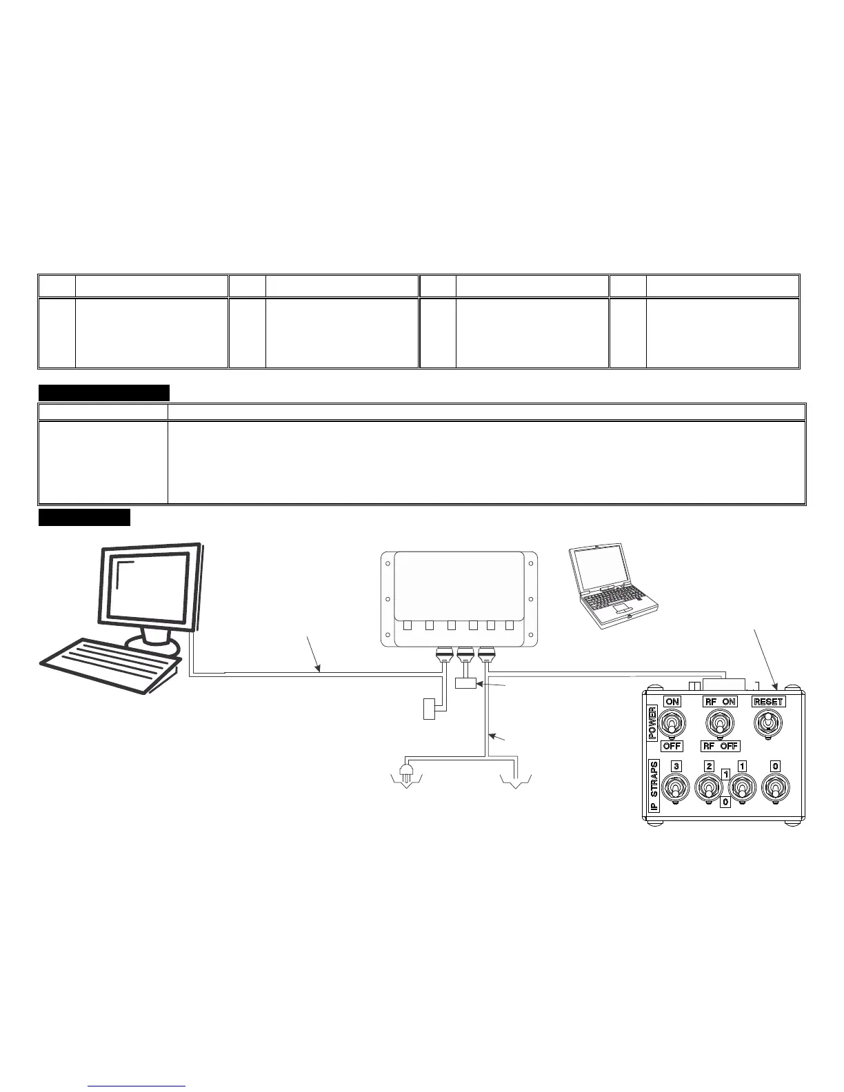
Connect the nMAP2 Access Point in the lab environment as shown:
ETHERNET
LAN PORT 1
28 VDC
(18 - 32 VDC)
INPUT POWER
OR
J2 TEST CABLE MILTOPE PART
NUMBER CT2014-017
USE OF J2 TEST CABLE IS
OPTIONAL FOR CONNECTION
TO AN ADDITIONAL COMPUTER
J1 TEST CABLE MILTOPE
PART NUMBER CT2014-016
WHAT IS IN THE BOX: nMAP-2 WIRELESS ACCESS POINT PART NUMBER 903920-1
EQUIPMENT REQUIRED, BUT NOT SUPPLIED:
DESKTOP COMPUTER WITH 10/100/1000 BASE TX ETHERNET CAPABILITY
LAPTOP COMPUTER WITH IEEE 802.11a/g (IEEE 802.11a/ac/g/n
RECOMMENDED) WIRELESS CAPABILITY AND SETTABLE WIRELESS MODE
TEST BOX, MILTOPE PART NUMBER CT2014-013
J1 TEST CABLE, MILTOPE PART NUMBER CT2014-016
J2 TEST CABLE, MILTOPE PART NUMBER CT2014-017
J3 TEST CABLE, MILTOPE PART NUMBER CT2014-018
P1
P6
(LAN
J1J2
P2
J3
P3
P5
USE OF P5 (LAN PORT 3) IS OPTIONAL FOR
CONNECTION TO AN ADDITIONAL COMPUTER
LAPTOP COMPUTER WITH
IEEE 802.11a/g CAPABILITY
(IEEE 802.11a/ac/g/n RECOMMENDED)
J3 TEST CABLE MILTOPE
PART NUMBER CT2014-018