EasyManua.ls Logo

VT Miltope nMAP2 - INSTALLATION

Default Icon
32 pages
Print Icon
To Next Page IconTo Next Page
To Previous Page IconTo Previous Page
Loading...
5
I. Refer to nMAP2 Wireless Access Point Operating Software
Operator’s Manual M365-768 for detailed instructions for
configuring the nMAP2 access point for a specific application.
NOTE: Selecting the country of operation during the configuration
process will limit radio configuration to settings that comply
with the regulatory requirements of the selected country.
The default country setting is USA.
The nMAP2 Wireless Access Point must be installed by personnel
qualified and authorized to install equipment aboard an aircraft.
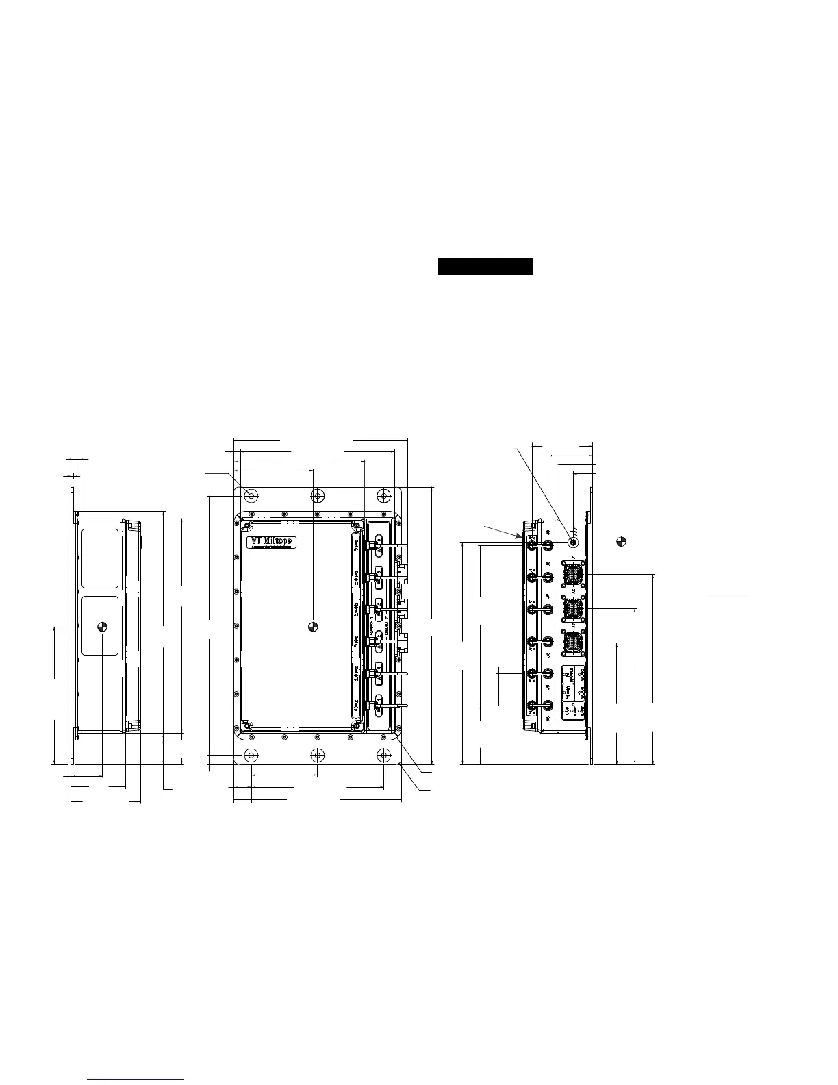
Mounting the nMAP2 Access Point As shown in the nMAP2 access
point outline drawing, six mounting holes are provided. Mount the
nMAP2 access point using number 10-24 mounting hardware.
Recommended torque value for mounting hardware is 24.0 inch-
pounds. Although not mandatory for specification compliance, it is
recommended that the nMAP2 access point be mounted to a grounded
surface within the aircraft. An unpainted area around each mounting
hole provides ground connection to the mounting surface.
NOTES:
1. Primary dimensions are in inches.
2. Dimensions in parenthesis are in millimeters.
3. Tolerances:
X.XX (2 Places) = ±0.04 (±1.02)
X.XXX (3 Places) = ±0.010 (±0.25)
4. denotes center of gravity.
5. Maintain minimum 2 inches (50.8 mm)
between nMAP2 and aircraft insulation on all
four sides and antenna radome surface.
1409231A
0.563 (14.29) MASKED
AREA AROUND
MOUNTING HOLES
FOR GROUNDING
6.39 (162.31)
0.733
(18.61)
6.97 (176.91)
0.38
(9.53)
3.30±0.25
(83.82±6.35)
7
.
3
5
(
1
8
6
.
6
9
)
M
A
X
11.50
(292.1)
0.29
(7.3)
2.750 (69.85)
5.500 (139.7)
10.750
(273.05)
4X R 0.43 (11.02) REF
4X R 0.25 (6.35) REF
6X 0.203 (5.16)
MOUNTING HOLES
9.47
(240.52)
1.02
(25.79)
1.30
±0.25
(
33.02
±
6.35)
5.70
±0.25
144.78
±6.35)
0.09
(2.29)
0.25
(6.3)
8.89
(225.81)
1.31
(33.15)
2.28
(57.79)
2.89 (73.35)
8-32 UNC-2B THREADED
GROUND POINT
0.28 (7.1) MAX
SCREW DEPTH
FROM FACE,
20±1.0 IN-LBS
MAX TORQUE
2
.
5
1
(
6
3
.
8
2
)
REF
1.85 (46.88) REF
0.80 (20.39) REF
2.44
(61.97)
REF
5.04
(128.07)
REF
6.46
(164.05)
REF
7.88
(200.03)
REF
1.33
(33.68)
REF
5X
6.63
(168.39)
REF
9.20
(233.56)
REF
5.43 (137.95)
1.47 (37.37)
WARNING
THE nMAP2 ANTENNA RADIATES
RADIO FREQUENCY (RF) POWER.
TO AVOID EXCEEDING FEDERAL
COMMUNICATIONS COMMISSION
(FCC) RADIO FREQUENCY
EXPOSURE LIMITS, HUMAN
PROXIMITY TO THE nMAP2 SHALL
BE NO LESS THAN EIGHT INCHES
(20 CENTIMETERS) WHILE RF IS
ENABLED.
ANTENNA
RADOME
nMAP2 Access Point Outline Drawing
INSTALLATION