4. After you’ve examined all the tubes to make sure that they are firmly placed in their sockets, you
can put the protective cage back onto the amplifier unit. Tighten the screws to make sure that
the cage is securely fastened to the unit.
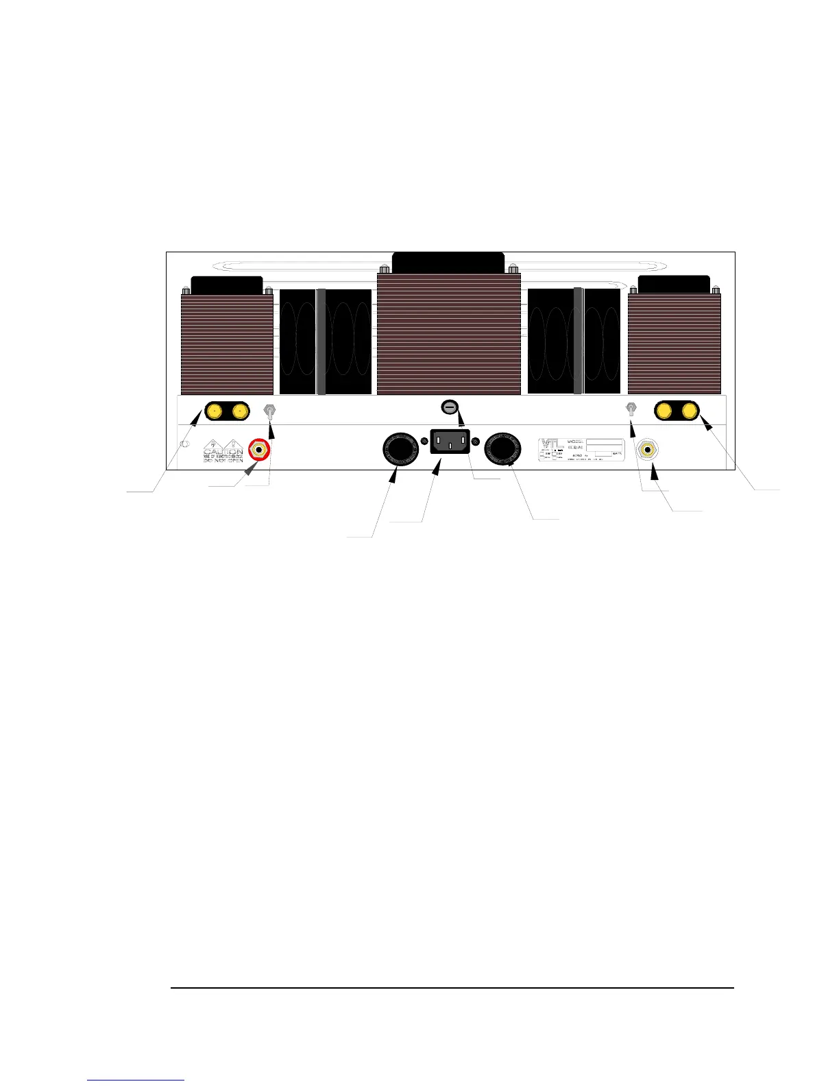
ST-150 Back Panel
TETRODE
SPEAKER
RIGHT CHANNEL
8A(120VAC) SLO-BLO
MAIN FUSE
4A(240VAC) SLO-BLO
TRIODE
+
-
SPEAKER
LEFT CHANNEL
Manufactured by:
Vacuum Tube Logic
4774 Murrieta Street
Suite 10, Chino, CA
91710, USA (909) 627-5944
TRIODE
TETRODE
+
-
Binding posts
B+ fuse
1A F 600V
RCA input
AC receptacle
AC POWER
INPUT
INPUT
Triode/Tetrode switch
WARNING
To prevent possible switch damage do not change mode
while amplifier is powered on.
on before making all connections.or speaker damage do not power
To prevent possible transformer
To prevent electrical shock do not remove cover.
No user servicable parts inside. Refer servicing
to qualified personnel. For continued protection
against fire hazard replace only with fuses of same
type and rating. To prevent fire or shock do not
expose this appliance to rain or moisture.
Stereo Power Amplifier
F
E
S
U
F
E
S
U
F
E
S
U
F
E
S
U
F
E
S
U
F
E
S
U
B+ FUSEB+ FUSE
RCA input
B+ fuse
1A F 600V
1A F 600V
1A F 600V
Triode/Tetrode switch
Binding posts
Mains fuse
12A(120VAC) SLO BLO
6A(240VAC) SLO BLO
The ST-150 Back Panel Silkscreen
Connecting Your Amplifier to your system
The ST-150 Stereo amplifier is a self-contained unit with the amplifier and power supply sections on one
compact chassis. Follow the instructions below to connect the amplifier to your audio or home theater
system:
1. Connect all source components (e.g. CD, Tuner, Tape, DAT, Turntable etc.) to the preamplifier.
Follow the instructions on your preamplifier and source component manuals to connect these
components together.
2.
Connect the power amplifier to the output channel of the preamplifier. The interconnect cable
between the amplifier and the preamplifier links the input channel of the power amplifier to the output
channel of the preamplifier. Connect the Left Channel RCA Jack from the Stereo amplifier to the left
output channel of the preamplifier. The same applies to the right channel of the amplifier.
3.
Select the input connector type. The amplifier supports only one type of input connector – the RCA
input. Place the interconnect cable firmly into the input jack which matches the type you have, and firmly
insert the interconnect cable into the input jack marked “INPUT”.
4.
Connect the loudspeaker cable to your amplifier. There is a pair of speaker binding posts in the back
of your amplifier for connecting your loudspeaker cables to the amplifier. These binding posts are marked
ST-150 Owner’s Manual
VTL
5
 Loading...