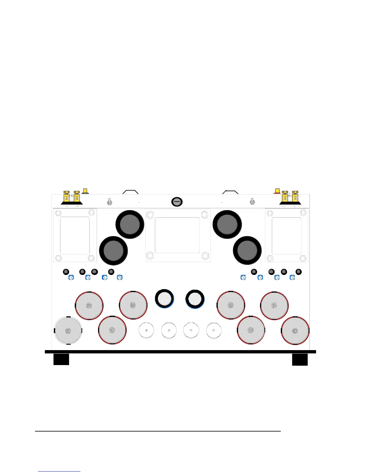
corresponds to the bias measurement point. See Figure below for the locations of the
measurement points.
2. Insert a 1/8” flat tipped screwdriver (with a plastic shaft or a properly insulated handle) into
the bias adjustment trimpot that corresponds to the out of range measurement point.
Rotate the screwdriver slowly to see the changes on the multimeter reading. Try rotating the
screw in both directions to see the effect of the change. Adjust the setting of the bias to the
proper range, i.e. 275 to 300 millivolts DC.
3. After you’ve completed the bias adjustment changes, it is a good idea to go back and check
the bias measurements for all the other tubes since changes made to one tube will slightly
affect the setting of the others.
4. Place the amplifier’s protective cage firmly back onto the amplifier after you are satisfied that
the measurements are stable.
ÎCaution: If your observations do not conform to the above instructions, or if you do not feel confident
about performing the bias procedures yourself, please consult with the VTL factory service
department. Improper setting of the bias will affect the current draw of the output tubes and affect
the performance and lifetime of the tubes.
Top view and Bias Measurement points of the ST-150 Amplifier
TRIODE
TETRODE
TRIODE
TETRODE
4A(230VAC) SLO-BLO
MAIN FUSE
8A(115VAC) SLO-BLO
WARNING
To prevent possible switch
damage do not change mode
while amplifier is powered on.
6550C
2
6550C
1
6550C
3
6550C
4
6550C
5
6550C
6
6550C
7
6550C
8
WARNING
To prevent possible transformer
or speaker damage do not power
on before making all connections.
12BH7 12AT7
12BH7
12AT7
MEASUREMENT POINT
BIAS ADJUST POINTS
1
2
3
4
5
67
8
1
234
5
67
8
ST-150 Owner’s Manual
VTL
10


 To Next Page