www.prolight.co.uk TPX Series Power Ampliers User Manual
4
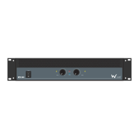
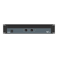
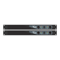
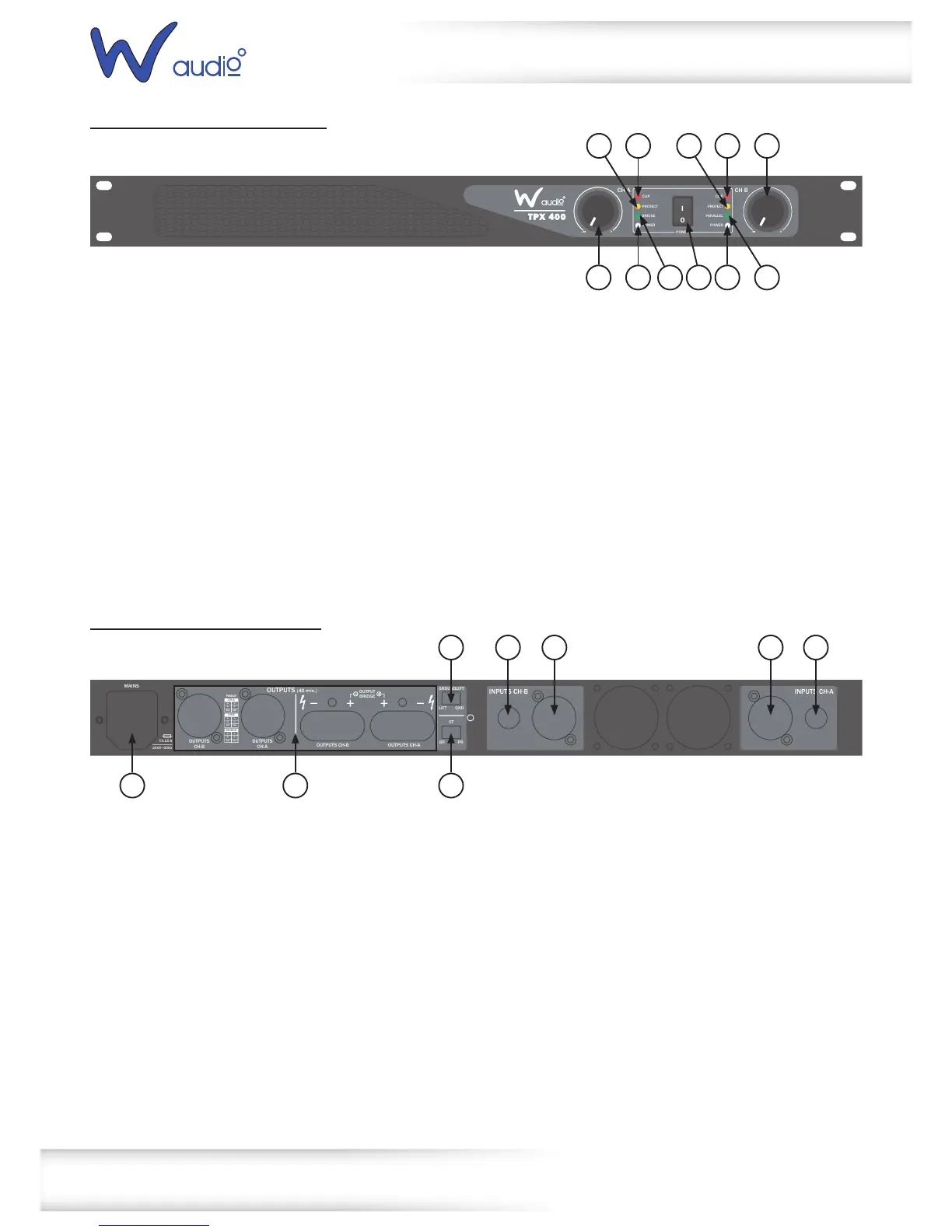
TPX 400 & TPX 650 front panel
TPX 400 & TPX 650 rear panel
Technical specications
01-ClipLEDs-TheseLEDsashredtoindicatewhenthe
outputoftheamplierhasreachedthemaximum,andis
rightontheedgeofclipping.Clippingisbadforspeakers
andshouldbeavoided.ItisokayiftheLEDblinks
occasionally.Itmeansthatthetransientpeaksofthe
musicarejusthittingthefulloutputoftheamplier.
02-Gaincontrol-Thesetwoknobscontrolthelevelsof
Channels1and2.Usually,thesecontrolsaresetallthe
wayup.Youmightturnthemdownslightlyifyouhave
high-efciencyspeakers.Also,youcouldusethemto
controlthelevelofline-levelsourcessuchasaCDplayer
connecteddirectlytotheamplierwithouta
pre-amplierormixer.Afteryouhavesetthelevels
forthemixer(orothersignalsource),adjusttheLevel
controlsontheamplierasthenaladjustmenttoset
theoverallvolumeforthesystem.
Instereoandmonomode,usebothlevelcontrolsto
controlthelevelsgoingtoeachspeaker.Inbridged
mode,turnthechannel2levelcontroldown,andjust
usethechannel1control.
03-PowerLEDs-TheseLEDsilluminatewhentheamplier
isswitchedon
04-ProtectLED-TheseLEDsilluminateduringoperation,
oneoftheprotectioncircuitsisactive.Pleasetakethe
amplieroutofoperationandhaveittested
05-BridgedLED-Thisilluminatesinbridgedmode
06-ParallelLED-ThisLEDilluminatesinparallelmode
07-Powerswitch-Pressthisswitchtostarttheoperation
PARALLEL
CLIP
PROTECT
BRIDGE
POWER
POWER
CLIP
PROTECT
POWER
I
O
CH A CH B
-
∞
0
-
∞
0
01 01 02
02 0703 03
04
06
04
05
01-XLRinputs-Theseinputsallowyoutoconnectbalanced
XLRplugs.Thesearewiredwithpin2hot,pin3coldand
pin1ground
02-¼”jackinputs-Theseinputsallowyoutoconnect¼”
unbalancedjackplugs
03-Therearetwowaysofconnectingyourspeakers:
Lockingspeakerconnectorsorbindingposts.
Theconnectorsarewiredinparallel.(e.g.Channel1
bindingpostandlockingspeakerconnectorsarein
parallelandthesameforchannel2).
Whentheamplierisusedinbridgedmonomodeyou
mustusethetworedbindingposts.
04-IECpowersocket-ThisiswhereyouconnecttheIEC
powercable.Connecttheotherendtoa240VACoutlet.
05-Ampmode-Thisswitchdeterminestheinputsignal
routingwithintheamplier.Formostapplicationsstereo
willbeused.
Stereo:Thisisthenormalmodeforamplifyingstereo
signals.Itacceptsleftandrightinputsandroutesthem
totheleftandrightoutputs.
Parallel:Thismodeisusedwhenyouwanttosend
monosignalstobothoutputs.Itacceptsasingleinput
intochannel1androutesittoboththechannel1and
channel2outputs.Eachchannelslevelcontroladjusts
thegainforeachchannel.
Bridge:Thismodeacceptsasingleinputintochannel1
andusesbothamplieroutputstodoublethepowerto
onespeakeroutput.Usechannel1levelcontroltoadjust
thegain.Turnchannel2levelcontroltominimum.
06-Groundliftswitch-Thisswitchallowsthesignalground
orchassisgroundtobeseparatedincaseofaground
conict.Forthehighestsafetyoftheequipment,itis
recommendedtokeepthe“groundliftswitch”inthe
GNDposition.Incaseofagroundconictpleaseset
thegroundliftswitchtoGNDLIFT.
OUTPUTS (4Ω min.)
MAINS
T3.15 A
240V~50Hz
GROUNDLIFT
LIFT GND
ST
BR PR
OUTPUTS
CH-B
OUTPUTS
CH-A
OUTPUTS CH-A
INPUTS CH-B INPUTS CH-A
OUTPUTS CH-B
OUTPUT
BRIDGE
PINOUT
CH-A
POS
1-
2-2+
1+
NEG
BRIDGE
POS
1-
2-2+
1+
NEG
CH-B
POS
1-
2-2+
1+
NEG
 Loading...