NOTE:
(1) Above electrical wiring diagram only for your reference, please subject machine posted the wiring diagram.
(2) The swimming pool heat pump must be connected ground wire well, although the unit heat exchanger is
electrically isolated from the rest of the unit. Grounding the unit is still required to protect you against short
circuits inside the unit. Bonding is also required.
Disconnect: A disconnect means (circuit breaker, fused or un-fused switch) should be located within sight of
and readily accessible from the unit. This is common practice on commercial and residential heat pumps. It
prevents remotely-energizing unattended equipment and permits turning off power at the unit while the unit
is being serviced.
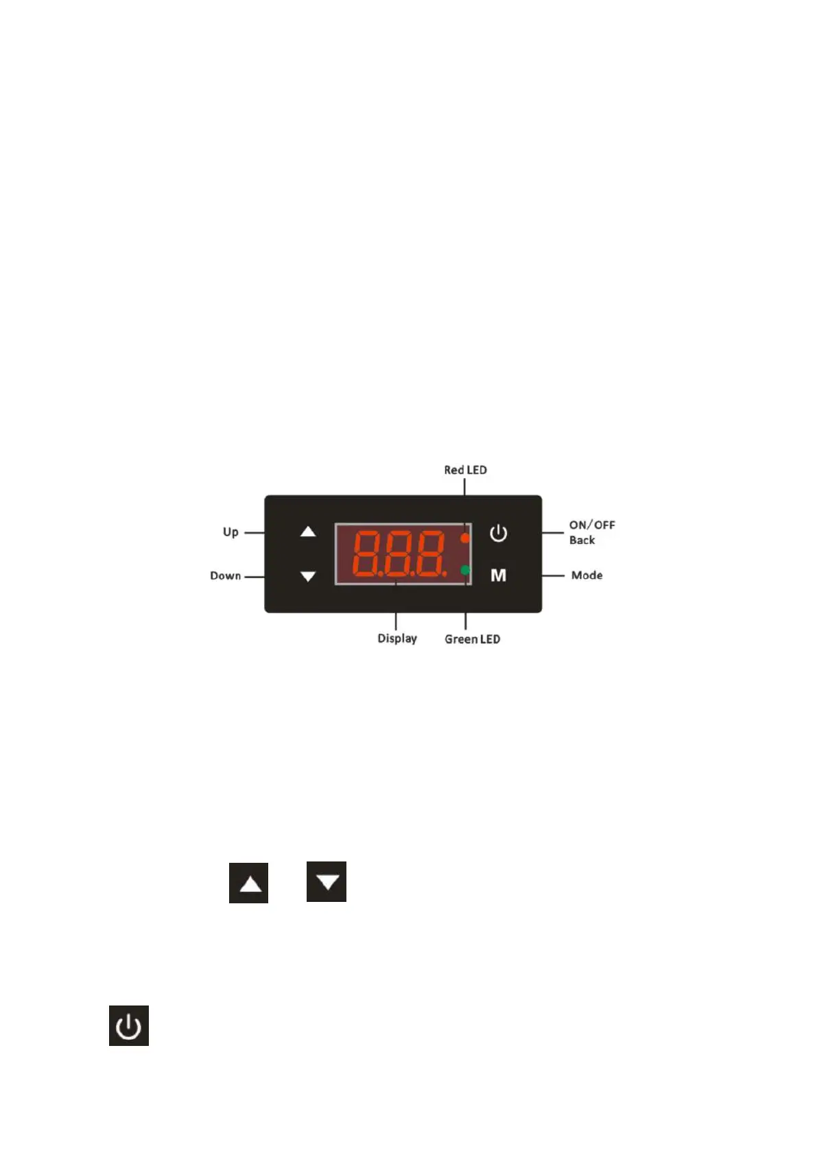
5. Display controller operation
5.1 The interface of LED wire controller
* When the heat pump is running or standby, the display shows the water inlet temperature.
* When the heat pump is Power-on, the display shows ‘OFF’
* Red LED will light on when machine under Heating mode
* Green LED will light on when machine under Cooling mode
* Red LED will flash when machine under defrosting
5.2 Lock/Unlock the display
NOTE: The display will be locked automatically if there is no operation on the display for 3 seconds!
Unlock the display: Hold and for 3 seconds until all buttons light on.
Please do unlock the display before you operate the display.
5.3 Turn on/off the heat pump
Hold for 2 seconds to turn on/off the heat pump