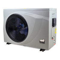
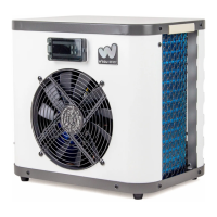
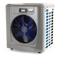
This document is an installation and operation manual for a MiniPool Heat Pump, Model YC-005TB1. It provides essential information for the proper installation, operation, and maintenance of the device.
The MiniPool Heat Pump is designed to heat swimming pool water. It operates as an air-source heat pump, extracting heat from the ambient air and transferring it to the pool water. The manual emphasizes that the unit must be installed by professional personnel according to the provided guidelines to ensure proper functioning and safety. Any use that does not conform to the original manufacturing specifications is considered dangerous.
Important Safety and Installation Guidelines:
- Professional Installation: The unit must be installed by qualified professionals following the instructions in this manual.
- Lightning Protection: If installed in an area vulnerable to lightning strikes, appropriate lightning protection measures must be implemented.
- Ventilation: The heat pump should always be kept in a well-ventilated area, away from anything that could cause fire.
- Refrigerant Handling: Do not weld pipes if refrigerant is inside the machine. Gas filling must be performed in a confined space. Action of filling gas must be conducted by professionals with an R410A operating license.
- Winterization: During winter or when ambient temperatures drop below 32°F (0°C), the water in the heat pump must be emptied. Failure to do so can damage the Titanium exchanger due to freezing, which will void the warranty.
- Electrical Safety: Always cut the power supply before opening the cabinet to access internal components, as high voltage electricity is present inside.
- Display Controller Protection: Keep the display controller in a dry area to prevent damage from humidity.
- Manufacturer Responsibility: The manufacturer disclaims any responsibility for damage to people, objects, or errors due to installation that disobeys the manual guidelines.
Technical Specifications (Model YC-005TB1):
The heat pump's performance varies with ambient air and water temperatures.
- Heating Capacity (80°F Air, 80°F Water, 63% RH): 16036 Btu/h
- Power Input (80°F Air, 80°F Water, 63% RH): 3599 Btu/h
- COP (80°F Air, 80°F Water, 63% RH): 4.45
- Heating Capacity (50°F Air, 80°F Water, 63% RH): 10747 Btu/h
- Power Input (50°F Air, 80°F Water, 63% RH): 3070 Btu/h
- COP (50°F Air, 80°F Water, 63% RH): 3.50
- Power Supply: 110-120V/60Hz
- Max Power Input: 4623 Btu/h
- Max Current: 7.1 A
- Setting Temperature Range (Heating): 59°F~104°F (15°C~40°C)
- Setting Temperature Range (Cooling): 46°F~82°F (7.8°C~27.8°C)
- Running (Air) Temperature Range: 23°F~109.4°F (-5°C~43°C)
- Refrigerant Type/Quantity: R410A/15.90 Ozs
- Air Side Heat Exchanger: Hydrophilic fin exchanger
- Water Side Heat Exchanger: Titanium tube heat exchanger
- Water Flow: 9.3 gpm
- Net Dimensions (L×W×H): 17×14×17 inches (432x356x432 mm)
- Packing Dimensions (L×W×H): 19×17×19 inches
- Net Weight: 59 lbs
- Packing Weight: 66 lbs
- Maximum Working Pressure of Heat Exchanger: 4.4 MPa
- Maximum Working Pressure of Exhaust Side: 4.4 MPa
- Maximum Working Pressure of Suction Side: 2.5 MPa
- Noise: 50dB(A)
Usage Features:
The heat pump is designed for easy operation via a display controller.
- Display Interface: When running or in standby, the display shows the water inlet temperature. When powered on, it shows 'OFF'. A light indicates when the machine is on.
- Defrosting Indicator: During defrosting, a snowflake icon will light up, and another icon will flash.
- Power On/Off: Press the power button to turn on the heat pump. The LED display will show the water setting temperature for 3 seconds, then revert to the water inlet temperature. Pressing the button again turns the unit off, and 'OFF' will be displayed.
- Compressor Delay: There is a 3-minute time delay protection for the compressor upon startup. If the unit is powered on for the first time or after additional power interruptions, it starts 10 seconds after pressing the 'ON/OFF' button.
- Temperature Setting: Use the up and down arrow buttons to adjust the desired water temperature. The new setting is saved after 3 seconds.
- Operating Condition: The heat pump operates only if the water circulation/filtration system is running.
- Temperature Units: Hold the 'M' button for 3 seconds to switch between Celsius (°C) and Fahrenheit (°F).
Electrical Connection:
- Voltage Verification: Before connecting, ensure the supply voltage matches the heat pump's operating voltage.
- RCD Plug: The power cable includes an RCD (Residual Current Device) plug for electrical protection.
- Secure Connection: Ensure the power plug is secure to prevent electric shock, overheating, or fire.
- Avoid Operation During Plug Removal: Never pull out the power plug during operation, as this can cause electric shock or fire.
- Use Undamaged Wires: Do not use damaged or unspecified electric wires to prevent electric shock or fire.
- Grounding: The swimming pool heat pump must be properly grounded, even though the unit's heat exchanger is electrically isolated. Grounding is essential for protection against short circuits. Bonding is also required.
- Disconnect Means: A disconnect means (circuit breaker, fused or un-fused switch) should be located within sight and readily accessible from the unit. This allows for safe power cutoff during servicing and prevents remote energizing of unattended equipment.
Condensation:
The air drawn into the heat pump is significantly cooled, which can lead to condensation on the evaporator fins. This condensation can amount to several liters per hour in high humidity conditions and should not be mistaken for a water leak.
Troubleshooting (Error Codes on LED Controller):
- P1 (Water temperature sensor failure):
- Reason: Water temperature sensor open circuit or short circuit.
- Solution: Check sensor wiring, replace the water temperature sensor.
- P3 (Piping temperature sensor failure):
- Reason: Piping temperature sensor open circuit or short circuit.
- Solution: Check sensor wiring, replace the piping temperature sensor.
- P5 (Ambient temperature sensor failure):
- Reason: Ambient temperature sensor open circuit or short circuit.
- Solution: Check sensor wiring, replace the ambient temperature sensor.
- E0 (Too low or too high ambient temperature protection):
- Reason: Ambient temperature is out of operating range (23°F~109.4°F), or controller failure.
- Solution: Wait for ambient temperature to recover, or replace the controller.
- E3 (Water flow failure):
- Reason: Insufficient or no water flow, loose wiring for water flow switch, or malfunction of water flow switch.
- Solution: Check water pump or piping system, check wiring of water flow switch, or replace water flow switch.
Troubleshooting (Other Malfunctions - No display on LED controller):
- Heat pump is not running:
- No power supply: Check cable and circuit breaker.
- LED wire controller displays actual water temperature:
- Water temperature is reaching setting value, HP under constant temperature status: Verify water temperature setting.
- Heat pump just starts to run: Start up heat pump after a few minutes.
- Short running:
- Fan NO running: Check cable connections between motor and fan, replace if necessary.
- Air ventilation is not enough: Check location of heat pump unit and eliminate obstacles to ensure good air ventilation.
- Water stains:
- Concreting: No action.
- Water leakage: Check the titanium heat exchanger carefully for defects.
Maintenance Features:
- Water Supply Check: Regularly check the water supply system to prevent air entry and low water flow, which can reduce performance and reliability.
- Pool and Filtration System Cleaning: Regularly clean your pools and filtration system to avoid damage to the unit from clogged filters.
- Winter Discharge: Discharge water from the heat pump if it will stop running for a long time (especially during the winter season).
- Pre-Run Check: Before starting the unit, ensure the unit is fully filled with water.
- Continuous Water Discharge: When the unit is running, there is always a small amount of water discharge.