1 Introduction
12
Meritor WABCO Maintenance Manual 34 (Revised 03-16)
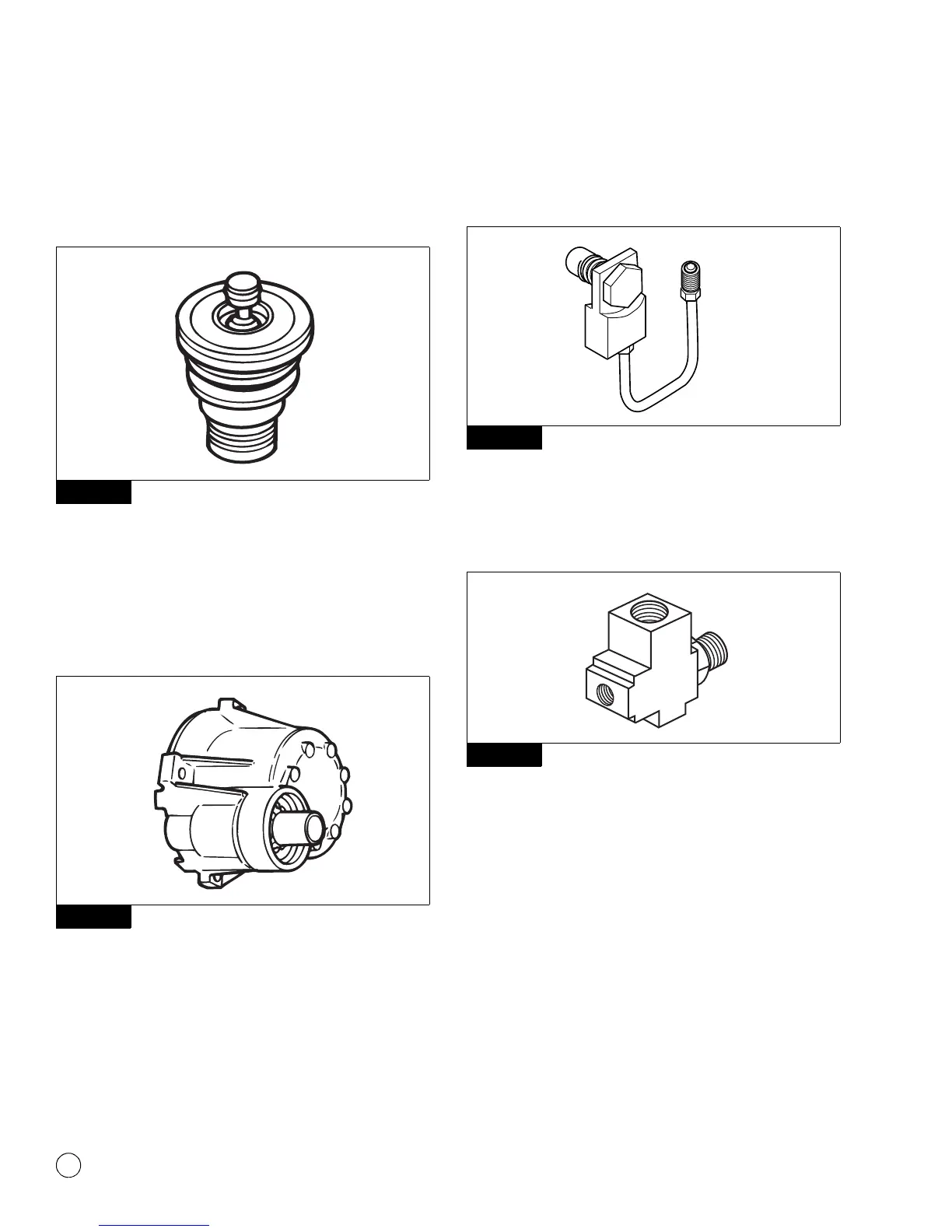
Purge Valve: A valve located on the bottom of the air dryer base
that remains open during a compressor unload cycle. It allows
collected moisture, condensation, and contamination to be expelled
from the air dryer during a purge cycle. Figure 1.17.
Figure 1.17
Regeneration Valve: The valve that controls regeneration of the
desiccant. It allows air from the supply and secondary tanks to
bypass the outlet check valve. The air expands and backflushes
moisture off of the desiccant, then out through the dryer’s purge
valve. Figure 1.18.
Used with 1200 Series air dryers only.
Figure 1.18
ECON Valve Replacement Part: This valve is used on System
Saver Series 1200E single cartridge air dryers used with Holset
E-type compressors. Figure 1.19.
Figure 1.19
ECON Valve: This valve must be installed if System Saver 1200
Series air dryers NOT DESIGNATED E are used with Holset E-type
compressors. This valve is not required on System Saver 1200 E air
dryers. Figure 1.20.
Figure 1.20
Turbo Cut-off Valve: A valve located in the inlet port of the air dryer.
It closes the path between the air compressor and the air dryer
purge valve during compressor unload. This prevents a loss of
turbocharger boost pressure during a compressor unload cycle,
thereby maintaining boost pressure for maximum engine
horsepower. Figure 1.21 and Figure 1.22 (used exclusively on the
1200 Plus model).
There is no spring in the turbo cut-off valve assemblies used on U
Series air dryers.
The System Saver E Series air dryers use a special turbo cut-off
valve. Refer to the air dryer parts book PB-8857AS for part number
information.
Figure 1.17
Figure 1.18
Figure 1.19
Figure 1.20