12
Introduction
1. Wear safe eye protection.
2. Park the vehicle on a level surface. Block the wheels to prevent the vehicle from moving.
The trailer must not be loaded during this component installation.
3. Drain the brake and suspension systems of air before starting this procedure.
4. Disconnect the electrical power before starting this procedure.
5. Start with connecting the GIO hub cable, P/N 894 600 161 2, into the ECU‘s GIO 1 port and push in until
the locking clip seats. Then, if using the optional lift axle indicator light cable, install another GIO hub
cable, P/N 894 600 161 2, into the ECU‘s GIO 2 port and push in until the locking clip seats. Refer to
Figures 1, 2 and 3 depending on the override functionality selected.
6. If the optional lift axle indicator light is not used, plug the pressure sensor cable, P/N 449 826 XXX 0
into the ECU‘s GIO port 2. If the lift axle indicator light is used, plug the cable into the hub cable port 1.
The bayonet connector end of the cable will plug into the pressure sensor, P/N 441 044 106 0. Refer to
Figures 1, 2 and 3, depending on the override functionality selected.
The pressure sensor must be attached to the ride bag air circuit of the trailer‘s air suspension in order to
determine the load on the trailer.
7. Connect the lift axle control valve cable, P/N 449 408 XXX 0 to the GIO hub cable port 2 that is plugged
into the ECU GIO 1 port. Push the cable in completely until the lock engages. The bayonet cable end
of the cable will connect to the lift axle control valve, P/N 463 084 050 0. Refer to Figures 1, 2 and 3,
depending on the override functionality selected.
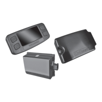
8. Ensure that the lift axle control valve is installed correctly. Refer to Figure 4.
A barrier of plastic or mylar should be placed between the lift axle control valve and the surface it
will be mounted on. This will help inhibit potential corrosion between dissimilar metals.
Fig. 4
4007073a
2.1 – TO THE
LIFTING
AIR BAGS
2.2 – TO THE
RIDE CONTROL
AIR BAGS OF
THE LIFTING
AXLE(S)
3.0 – EXHAUST
OUTLET
THIS SIDE UP
1.1 – SUPPLY
PRESSURE
1.2 – FROM THE
SUSPENSION
AIR BAGS OF
THE NON-
LIFTING AXLE(S)