28
Appendix III
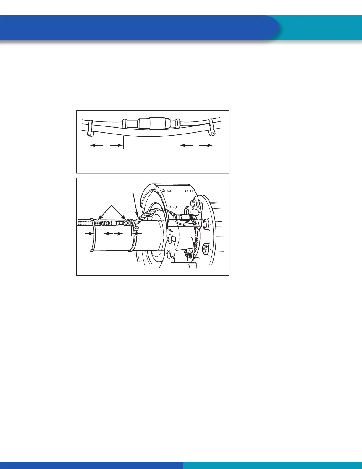
6.1.5 Cable-to-Cable Connections
It is important to ensure all cable-to-cable connections maintain good strain relief. Cable restraints must
be placed between 2- and 4-inches (51-102 mm) from the cable connector to ensure correct strain relief.
Regardless of whether zip ties or cable clips are used, cables should be secured at intervals not greater
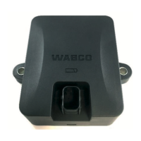
than 18-inches (457 mm) to avoid cable vibration. Refer to Figure 22 for air line attachment and Figure 23
for axle attachment.
Fig. 22
4012336a
3"
(76 MM)
3"
(76 MM)
ZIP TIES ON AIR LINES
Fig. 23
4011417a
3"
(76 MM)
SENSOR
CABLE
ZIP TIES ON AXLE
7 Appendix III
7.1 Vehicle Electrical Grounding Guidelines
Ensure that the vehicle includes a correct common chassis ground point. A common chassis ground point
connects the trailer frame/chassis to the ground pin of the J560 seven-way connector and will protect the
vehicle electrical system from unwanted electrical noise.
Common chassis ground can be veri ed by measuring the resistance between the J560 ground pin and
the vehicle chassis (or frame) and con rming that the resistance is less than 10 Ohm (<10 Ω). If this is not
the case, the electrical contact at the common chassis ground point is not suf cient or not present. If a
common chassis ground point is present, but not suf cient, ensure that there is no paint or debris inhib-
iting electrical contact at the ground point. If a common chassis ground point is not present, WABCO
recommends adding one.
NOTE: Do not add more than one common chassis ground point (connecting the J560 ground pin to the
chassis) to avoid potential ground shifts within the vehicle electrical system.