26
Appendix II
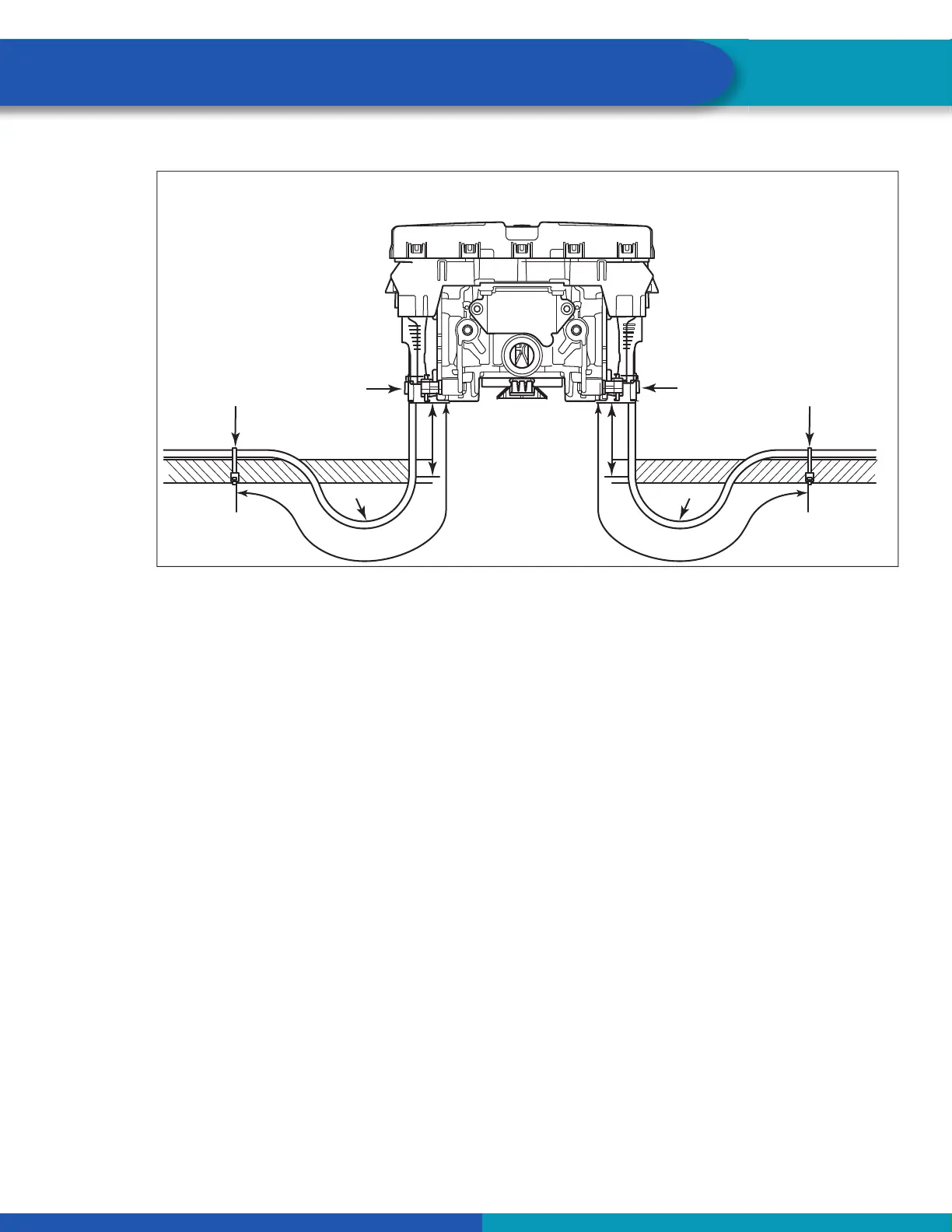
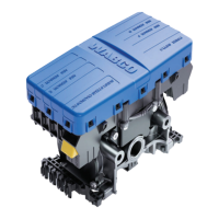
Fig. 19
4014395a
4"
Max.
12"
R
4"
Max.
12"
R ≥10 x D
R
FASTENER
FASTENER
ZIP TIE
ZIP TIE
Bend radius (R) equal to
or greater than 10 times
cable diameter (D).
R ≥10 x D
First fastener must be
a minimum 6 inches (152 mm)
and a maximum of 12-inches
(305 mm) from connector.
BRACKET MOUNTING - ECU REAR VIEW
4014395a
ABS 2S/2M-4S/3M
6.1.3 Strain Relief at the ECU — Tank Mounting
It is necessary that cable connections to a component, such as an ECU valve assembly, display a visible
amount of slack in the cable up to the rst tie or clip that secures the cable to the trailer structure or air
line. This rst anchor point should be a minimum 6-inches (152 mm) of cable length from the cable/com-
ponent connection and a maximum of 12-inches (305 mm). This applies to all sensor, power, valve and
GIO cables. Regardless of whether zip ties or cable clips are used, cables should be secured at intervals
not greater than 18-inches (457 mm) to avoid cable vibration.
Ideally, cables should be af xed to the rigid structure of the trailer. However, structure is not always avail-
able on tank-mounted installations. In these cases, securing the cable may be accomplished by fastening
the cable to nearby air lines. It is important to note that cables should be secured only to the extent that
the cable is held suf ciently in place. Refer to Figure 20 for 2S/2M-4S/3M ABS.