3-64 OM 25-3503 us – Edition 4.1 * * 2503_3503b330.fm
Operation
☞ Follow the safety instructions for assembly
– see chapter 3.39 Loading and transporting the machine on page 3-62.
☞ Lower the boom slightly.
☞ Stop the engine.
☞ Remove the starting key.
☞ Raise the control levers.
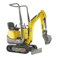
☞ Install the lifting gear at the points on the cabin provided for lifting the machine.
☞ Required lengths L1 of the lifting gear.
☞ Raise the cabin until the lifting gear is taut.
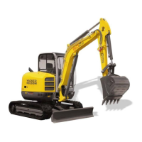
☞ Remove central plug B (X28) from the cabin wiring.
➥ Central plug B is located at the rear right next to the seat in the cabin.
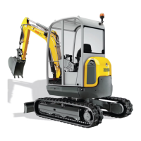
☞ Remove the hose of the washer fluid tank from non-return valve C.
➥ Non-return valve C is located at the front right under the engine cover.
Information!
Removing non-return valve C is not necessary if the machine is equipped with
a canopy. Depending on options, central plug B must also be removed.
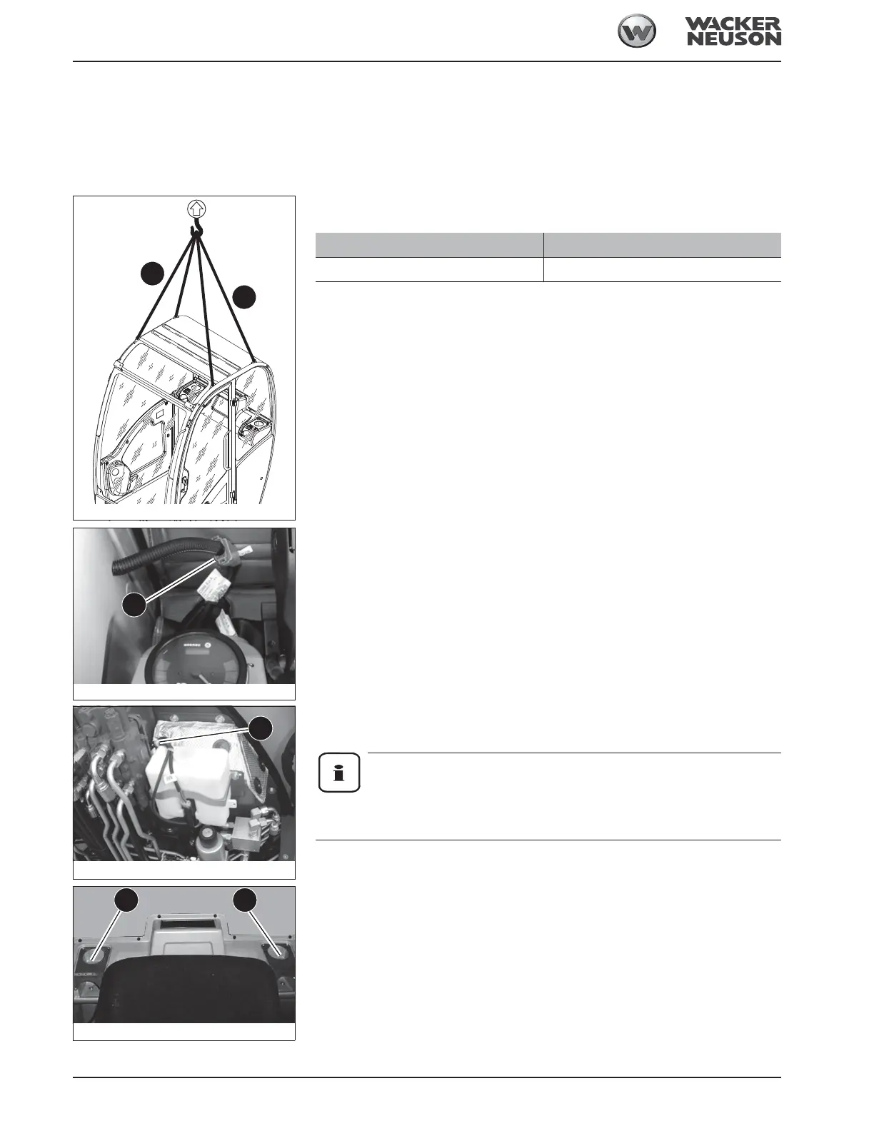
☞ Remove both screws E.
Fig. 155: Installing lifting gear
L1
L1
Length Dimension
L1 1000 mm (39 in)
Fig. 156: Central plug
B
Fig. 157: Washer fluid tank hose
C
B
C
Fig. 158: Cabin attachment
E E