Repair Engine and Upper Machine Components
wc_tx001546gb.fm 35
Continued from the previous page.
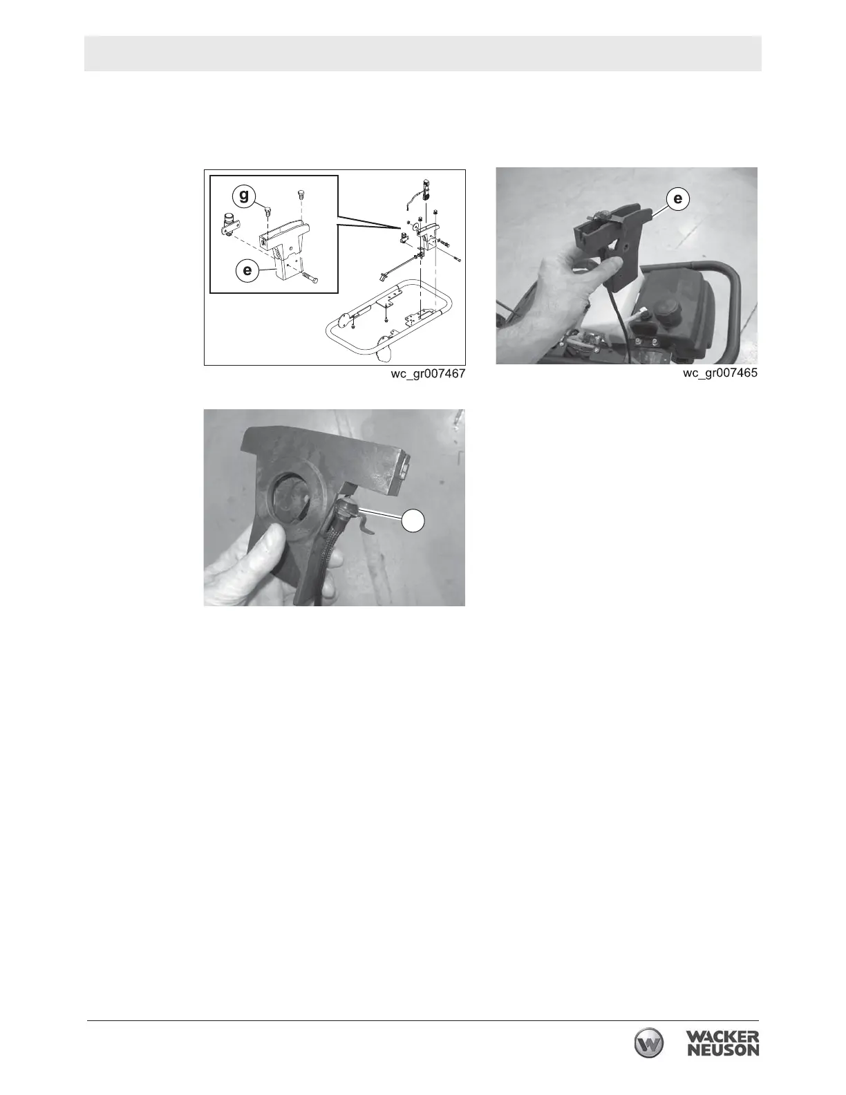
4.5.6 Remove the screws (g) that hold the throttle control bracket to the
machine and pull the throttle control bracket (e) (with stop switch) from
the machine.
4.5.7 Pull the stop switch
(f) and wiring from the throttle control bracket.
Result
The removal procedure is now complete.
Installation
Perform the procedure below to install the stop switch.
4.5.1 Slide the stop switch
(f) into the throttle control bracket (e) and thread
the wiring through the throttle control bracket.
This procedure continues on the next page.
wc_gr007466
f
 Loading...