5A-18
5A G3.3A/G4.6A/GS4.6A/GS5.7A 50 HZ PORTABLE GENERATORS
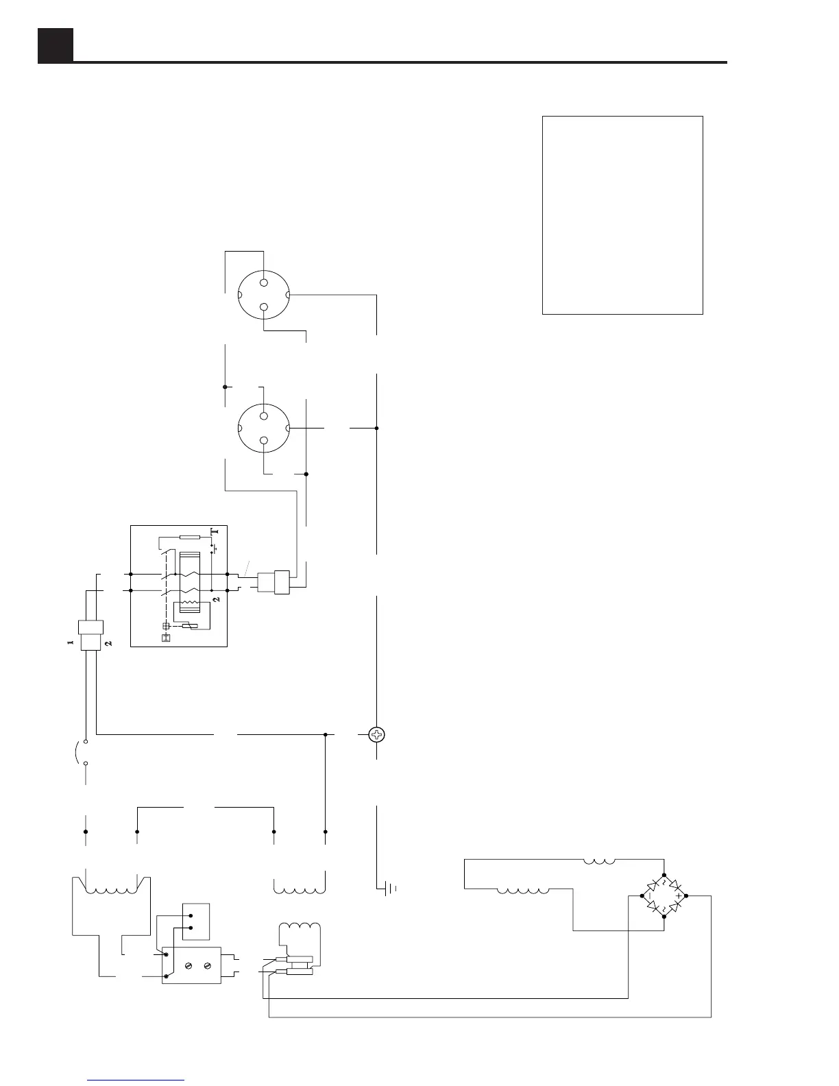
Generator Wiring Schematic (G4.6A, GS4.6A Models)
1020SD85
4
3
1
2
F2
F1
4
Z1
Z1
Z2
Z2
R
W
LL/B
R/B
R/Gr
LL/B
LL/Gr
G/Y
G/Y
L
Br
B
R
4
3
2
8
9
7
6
5
1
3
L1
L2
F1
F2
Z3
Z3
R/W
1
R
1
2
4
R/B
G/Y
R/B
G/Y
1
LL/B
LL/W
LL/W
Br
G/Y
1 = Main stator winding
2 = Main circuit breaker
3 = Earth-leakage circuit breaker (G4.6AE, GS4.6AE only)
4 = 16 Amp receptacle
5 = Choke
6 = Auxiliary winding
7 = Rotor winding
8 = Radio interference suppressor
9 = Automatic voltage regulator
Wire Colors
B - Black
G - Green
L - Blue
P - Pink
R - Red
LL-Light blue
W- White
Y - Yellow
Br - Brown
Gr - Gray
Or - Orange
Pr - Purple
T - Tan