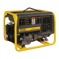
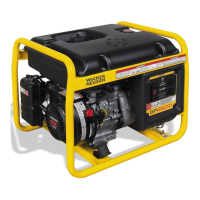
Schematics GP 3800A
54 wc_tx001777gb.fm
7.3 CSA Machines—Electrical Schematic
Ref. Description Ref. Description
A Generator E Honda Engine
B Control box
C Electric start engines (GPS)
Ref. Description Ref. Description
1 Main stator winding 1 12 Engine ON / OFF switch
2 Main stator winding 2 13 Rectifier
3 Auto idle unit 14 Rotor winding/brushes
4 Main circuit breaker 15 Secondary (excitation) winding
5 Voltage selector switch
(120/240V position shown)
16 DC winding
6 Duplex receptacle—120V 17 Automatic voltage regulator (AVR)
7 Twist-lock receptacle—120V 18 15A fuse (GPS only)
8 Twist-lock receptacle—120/240V 19 Ignition switch (GPS only)
9 Auto idle switch 20 GFCI
10 5A fuse 21 Neutral bond wire
11 Capacitor
 Loading...
