PerfectPower Technical description
31
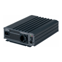
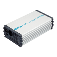
7.1 Control elements
Front view (fig. 1, page 3):
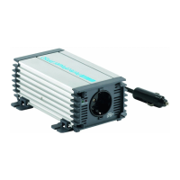
Rear view (fig. 2, page 3):
No. Description
1 Grid: This LED lights up if the inverter is supplied with external 230 V
mains power; the priority circuit is active.
2 Connection for the external 230 V power supply
3 Circuit breaker: Fuse
4 230 V AC output
5 POWER: This LED lights up when the inverter is switched on.
6 OLP: This LED lights up when the consumers connected draw too
much electricity.
7 UVP: This LED lights up when battery capacity is too weak.
8 OVP: This LED lights up when the input voltage is too high.
No. Description
1 Main switch
2 Connection for MCR-9 remote control
3 Connection for
external switch
4 Earth connection
5Fan
6 Negative terminal
7 Positive terminal
_PP1000_PP2000.book Seite 31 Dienstag, 6. April 2010 4:31 16
 Loading...