WAGO-I/O-SYSTEM 750 Process Image 27
750-530 8DO 24V DC 0.5A
Manual
Version 1.2.0
Pos: 70 /A ll e Ser ien (Al lg emei ne M od ule)/ Üb ers chrif te n für al le S eri en/ __ n och ni c ht ei ns orti ert e Üb ers chrif te n m üss en n och eins orti er t wer den __/ Proz ess a bbil d - Ü bersc hri ft 1 @ 4\mod_1240983067828_21.docx @ 31942 @ 1 @ 1
4 Process Image
Pos: 71 /S eri e 7 50 ( WA GO-I/ O-SYST EM) /Proz essab bild Kl emme nbus/H inwei s: Pro zessa bbild mappi ng abh ängig v on FBK/ PFC, o hne Stat us-/C ontr olby te @ 6\mod_1256126797251_21.docx @ 43340 @ @ 1
Mapping of process data in the process image of fieldbus systems
The representation of the process data of some I/O modules or their variants in the
process image depends on the fieldbus coupler/controller used. Please take this
information from the section “Fieldbus Specific Design of the Process Data”
included in the description concerning the process image of the corresponding
fieldbus coupler/controller.
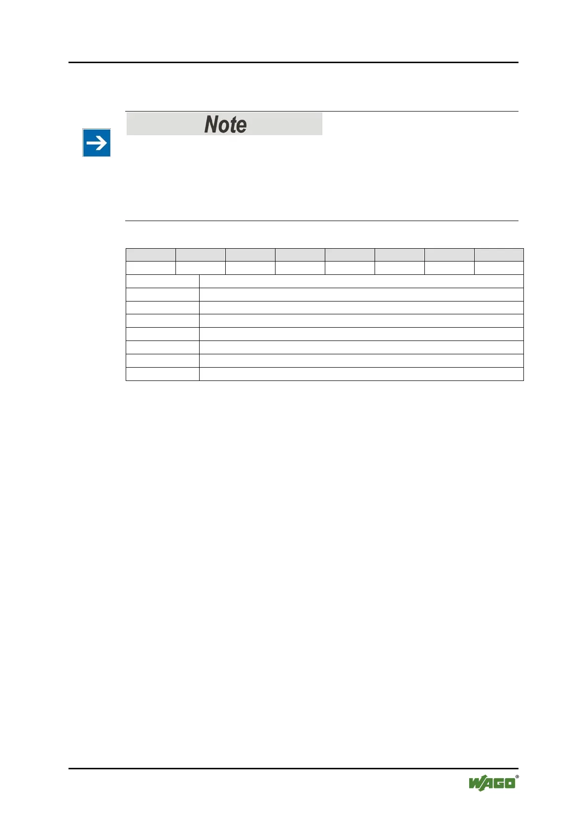
Pos: 72 /S eri e 7 50 ( WA GO-I/ O-SYST EM) /P roz ess abbil d Kl e mmen bus /Dig ital ausg ang s kle mme n/Pr ozes sab bild 75 0- x5xx 08 D O @ 4\mod_1236259349828_21.docx @ 28024 @ @ 1
Signal state DO 1 – Digital output channel 1
Signal state DO 2 – Digital output channel 2
Signal state DO 3 – Digital output channel 3
Signal state DO 4 – Digital output channel 4
Signal state DO 5 – Digital output channel 5
Signal state DO 6 – Digital output channel 6
Signal state DO 7 – Digital output channel 7
Signal state DO 8 – Digital output channel 8
Pos: 73 /Doku ment ation all gemei n/Gli eder ungsel eme nte/---Seit en wechs el--- @ 3\mod_1221108045078_0.docx @ 21810 @ @ 1
 Loading...


