Home
WAGO
Circuit breakers
EPSITRON 787-1668 Series
WAGO EPSITRON 787-1668 Series User Manual
4
of 1
of 1 rating
48 pages
Give review
Manual
Specs
To Next Page
To Next Page
To Previous Page
To Previous Page
Loading...
EPSIT
RON®
Notes about
this
Docum
entation
7
787
-
1668
Electron
ic Circui
t Break
er
Manual
Version 1.
1.0
Additional Information:
Refers to additional information which is not an integral part of this
documentation (e.g., the Internet).
Pos:
12.5
/Dokumentat
ion allgem
ein/Gliede
r
un
gselement
e/
---
Seit
en
wechs
el
---
@ 3
\
mod_122110
8045078_0.do
c
x @ 21810
@ @ 1
6
8
Table of Contents
Deutsch
3
Table of Contents
3
1 Notes about this Documentation
5
Validity of this Documentation
5
Copyright
5
Table 1: Versions
5
Symbols
6
Number Notation
8
Font Conventions
8
Table 2: Number Notation
8
Table 3: Font Conventions
8
2 Important Notes
9
Legal Bases
9
Subject to Changes
9
Personnel Qualifications
9
Use of the 787 Series in Compliance with Underlying Provisions
9
Technical Condition of Specified Devices
10
Safety Advice (Precautions)
11
3 Device Description
13
Table 4: Fuse Protection of Output Channels
13
View
14
Table 5: Key for "Device View" Figure
14
Connectors
15
Power Supply
15
Table 6: Power Supply Connections
15
Table 7: Power Supply Connections
15
Fuse-Protected Outputs
16
Control and Signaling Contacts
16
Table 8: Connections - Fuse-Protected Outputs
16
Table 9: Connections - Control and Signaling Contacts
16
Display Elements
17
Table 10: Legend for "Indicators" Figure
17
Operating Elements
18
Buttons
18
Rotary Switch
19
Table 11: Rotary Switch Settings
19
Technical Data
20
Device Data
20
Table 12: Device Data
20
Technical Data for "Input
21
Table 13: Technical Data - "Input
21
Technical Data for "Output
22
Table 14: Technical Data - "Output
22
Technical Data for "Ambient Conditions
23
Technical Data for "Signaling
23
Table 15: Technical Data - "Ambient Conditions
23
Table 16: Technical Data - "Signaling
23
Approvals
24
Standards and Guidelines
25
4 Mounting
26
Mounting the Device on the DIN 35 Rail
26
Removing the Device from the DIN 35 Rail
27
5 Connect Devices
28
Connection Example
28
6 Function Description
29
Undervoltage and Overvoltage Detection
29
Trip Curves
29
Trip Curve for the 10 a Circuit Breaker 787-1668
29
Trip Curve for the 6 a Circuit Breaker 787-1668/0106-0000
30
Trip Curve for the 6 a Circuit Breaker with Active Current Limitation 787-1668/0006-1000
30
Response of the Electronic Circuit Breaker with Active Current Limitation
31
Response 1: Over-Current Present that Is Greater than Threshold 3
32
Response 2: Over-Current Present that Is Greater than Threshold 1, but Less than Threshold 2
32
Response 3: Over-Current Present that Is Greater than the Nominal Current, but Less than Threshold 1
32
Selective Immediate Deactivation
32
Activating Capacitive Loads
33
Reference Values for 787-1668 and 787-1668/0106-0000
33
Reference Values for 787-1668/0006-1000
33
Table 17: Standard Reference Values for 787-1668 and 787-1668/0106-0000
33
Table 18: Standard Reference Values for 787-1668/0006-1000
33
Operating Statuses, Signaling, Reactions
34
Table 19: Operating Statuses, Signaling, Reactions
34
ON Delay for Specific Channels
36
Control Input S1
37
Re-Activating Tripped Channels
37
Specific Activation and De-Activation of Non-Tripped Output Channels
38
Table 20: Bit Allocation for Control Input S1
38
Table 21: Key for the "Standard 17-Bit Protocol" and "Extended 89-Bit Protocol
41
Signal Output S2
42
Table 22: Bit Allocation for Signal Output S2
43
Functioning of Communication between Control Input S1 and Signal Output S2
44
Signal Output S3
45
English
46
Default Chapter
14
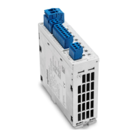
Figure 1: View of Device
14
Figure 2: 24 V Input
15
Figure 3: 0 V Input
15
Figure 4: Fuse-Protected Outputs Ch1
16
Figure 5: Control and Signaling Contacts
16
Figure 6: Indicators
17
Figure 7: Buttons
18
Figure 8: Rotary Switch
19
Figure 10: Mounting the Device on the DIN 35 Rail
26
Figure 9: Mounting the Device on the DIN 35 Rail
26
Figure 11: Removing the Device from the DIN 35 Rail
27
Figure 12: Removing the Device from the DIN 35 Rail
27
Figure 13: Connection Example
28
Figure 14: Trip Curve for the 10 a Circuit Breaker 787-1668
29
Figure 15: Trip Curve for the 6 a Circuit Breaker 787-1668/0106-0000
30
Figure 16: Trip Curve for the 6 a Circuit Breaker with Active Current Limitation
30
Figure 18: Example of Re-Activation Via Control Input S1, or Signal Output S3
37
Figure 19: Standard 17-Bit Protocol
40
Figure 20: Extended 89-Bit Protocol
40
Figure 21: Example of a Pulse Pattern at Control Input S1 and Signal Output S2
44
Figure 22: Cyclic Over-Current Pulse
44
List of Figures
46
List of Tables
47
4
Based on 1 rating
Ask a question
Give review
Questions and Answers:
Need help?
Do you have a question about the WAGO EPSITRON 787-1668 Series and is the answer not in the manual?
Ask a question
WAGO EPSITRON 787-1668 Series Specifications
General
Brand
WAGO
Model
EPSITRON 787-1668 Series
Category
Circuit breakers
Language
English
Related product manuals
WAGO 787-1668/0000-0080
58 pages
WAGO 787-2861 Series
46 pages
 Loading...