4
Specifications
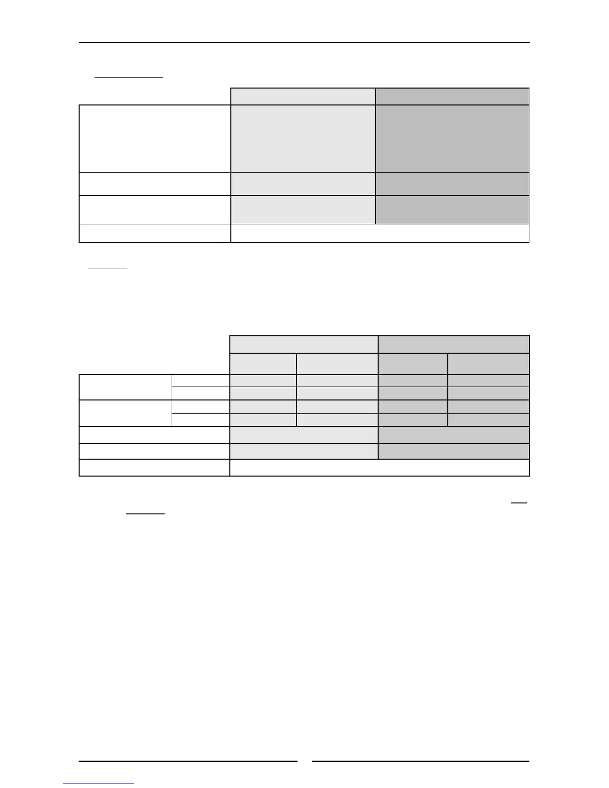
Gas Supply Requirements
- Non CE Only:
- CE Only:
Appliance Classification
Category: II
2H3P
(20, 30 / 37).
Flue Type: A
1.
* - The burner operating pressure is to be measured at the manifold test point with two
burners operating at full setting. The operating pressure is ex-factory set, through the
appliance regulator and is not to be adjusted, apart from when carrying out gas
conversion, if required. (Refer to the ‘Gas Conversion’ section for details).
Gas Connection
Gas supply connection point is located at the rear of the appliance, approximately 130 mm from the
right hand side, 35 mm from the rear and 655 mm from the floor and is reached from beneath the
appliance. (Refer to the ‘Dimensions’ section).
Connection is ¾" BSP male thread.
Natural Gas (G20) Propane (G31)
Open Burner
(each)
Griddle
(each 300mm section)
Open Burner
(each)
Griddle
(each 300mm section)
Heat Input
(nett)
Nominal 6.5 kW 5.5 kW 6.5 kW 5.5 kW
Reduced 1.75 kW 1.85 kW 1.75 kW 1.95 kW
Gas Rate (nett)
Nominal 0.69 m
3
/hr 0.58 m
3
/hr 0.51 kg/hr 0.43 kg/hr
Reduced 0.19 m
3
/hr 0.20 m
3
/hr 0.14 kg/hr 0.15 kg/hr
Supply Pressure 20 mbar 30 /37 mbar
Burner Operating Pressure 9.5 mbar (*) 26 mbar (*)
Gas Connection See ‘Gas Connection’ information overleaf
Natural Gas LP Gas (Propane)
Input Rate (N.H.G.C.)
- each Open Burner
28 MJ/hr
(26,540 Btu/hr)
28 MJ/hr
(26,540 Btu/hr)
- each 300 mm Griddle Section
21 MJ/hr
(19,900 Btu/hr)
21 MJ/hr
(19,900 Btu/hr)
Supply Pressure
1.13 - 3.40 kPa
(4.5” - 13.5” w.c.)
2.75 - 4.50 kPa
(11” - 18.0” w.c.)
Operating Pressure
0.95 kPa (*)
(3.7” w.c.)
2.6 kPa (*)
(10.0” w.c.)
Gas Connection
3
/
4
” B.S.P. Male
 Loading...