37
Pro Dry Instruction Manual | Walker Filtration | www.walkerltration.com
Section 7: Energy Management
Energy Management
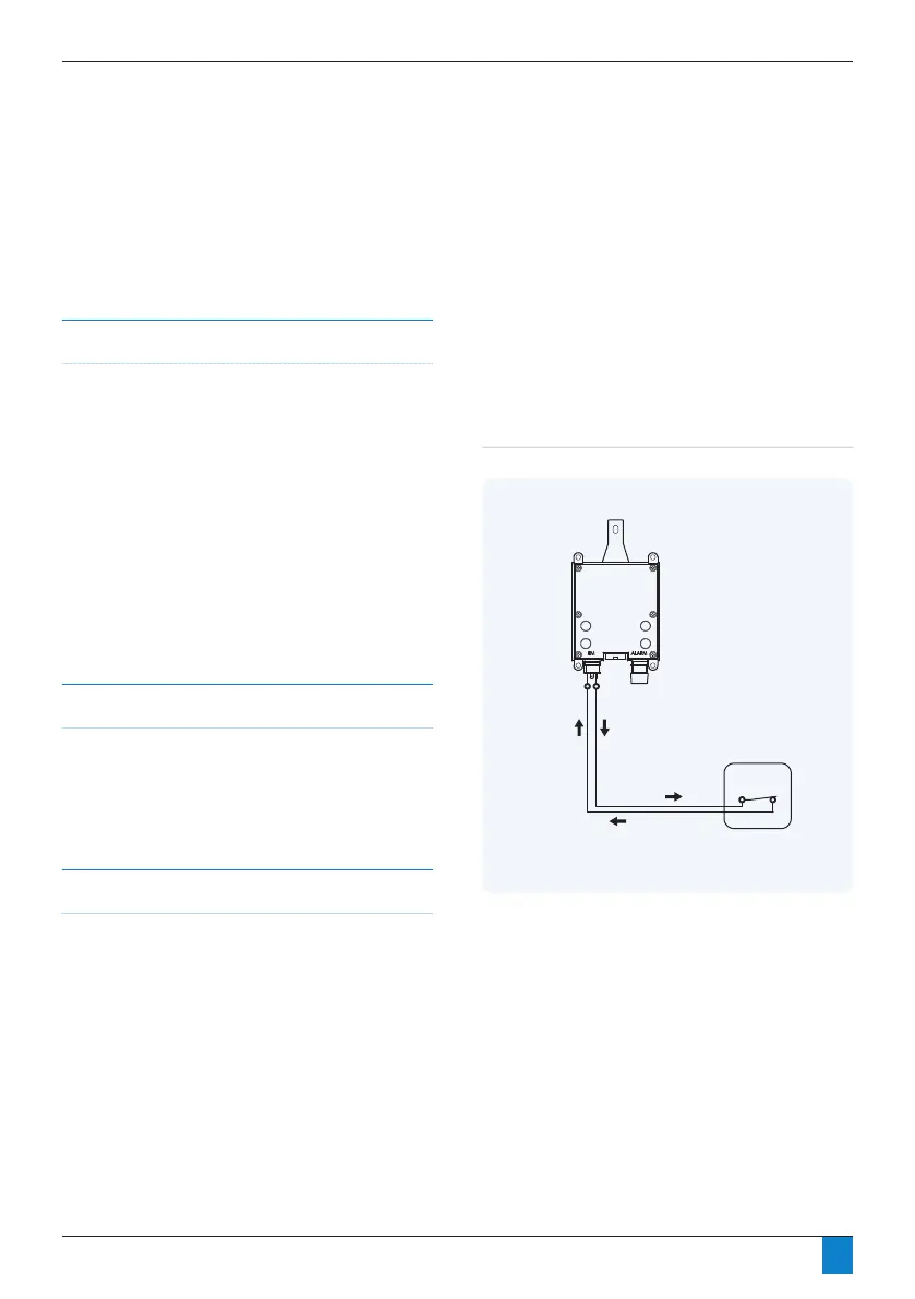
Fig 7. 1 Manual switch purge control
Overview
Regenerative dryers must expel a portion of the process air
in order to free themselves of accumulated moisture. During
periods of low air demand, however, this air loss is not
necessary and is therefore undesirable. In many cases, the
compressor runs almost continuously in order to keep up with
the dryer’s purge loss.
All Walker Filtration dryers are equipped with an Energy
Management feature that allows the purge to be shut off
during periods of low or no demand. The dryer controller
is tted with a set of eld accessible contacts, that can be
employed to shut off the solenoid valves which control the
purge function of the dryer, therefore eliminating any air loss
from the dryer.
Developing a Purge Control Strategy
In order to utilise this function, the operator must provide a
switching system that provides acceptable logic to indicate to
the dryer that there is little or no air demand. On the following
pages, some examples of commonly used switching systems
are provided in ascending order of complexity.
Using a Manual Switch for Purge Control
The simplest of arrangements, a manual switch may be
employed to shut the purge off when the air downstream of
the dryer is not being used. Commonly used on point of use
systems. For example, if the dryer is only used to supply air of
an appropriate dryness to a specic machine or application,
the dryer will only be required when the machine is in use and
may be shut off either manually or possibly via extra contacts
provided in the machine’s on/off switch.
It is extremely important to understand that the purge may
only be shut off during periods of low or no demand. This
feature, if used otherwise, can result in permanent damage
to the desiccant beds resulting in loss of drying capacity
and possibly mechanical failure. The cartridges must not be
allowed to become fully saturated at any time.
DRYER
CONTROLLER
DC POWER
SUPPLY
ELECTRONIC
PRESSURE SWITCH
RELAY
* Normally Closed, open to turn purge off
PIN 1 (puts out
+5 VDC signal)
PIN 2
SIGNAL BACK
SIGNAL OUT
N.C.*
N.O.
N.C.*
N.C.*
N.O.
* Normally Closed, open to turn purge off
MANUAL SWITCH
(Field Installed)
DRYER
CONTROLLER
PIN 1 (puts out +5 VDC signal)PIN 2
SIGNAL BACK
SIGNAL OUT
* Normally Closed, open to turn purge off
MANUAL SWITCH
(Field Installed)
DRYER
CONTROLLER
PIN 1 (puts out +5 VDC signal)PIN 2
SIGNAL BACK
SIGNAL OUT
COM
SIGNAL OUT
+VDC
+VDC
-VDC (COM)
DRYER
CONTROLLER
* Normally Closed, open to turn purge off
PROCESS
CONTROLLER
DC POWER
SUPPLY
DEW POINT
TRANSMITTER
RELAY
PIN 1 (puts out
+5 VDC signal)
PIN 2
SIGNAL BACK
SIGNAL OUT
SIGNAL
+VDC
COM
N.C.*
N.O.
COM
SIGNAL OUT
SIGNAL IN
+VDC
+VDC
-VDC (COM)
The following schematic ( Fig 7.1) offers an overview of the
devices mentioned as they might be connected for use in
controlling a dryer’s purge function. Please note that specic
details differ between device manufacturers, so in all cases the
manufacturer’s specications should be adhered to.
 Loading...