16
Pro Dry Instruction Manual | Walker Filtration | www.walkerltration.com
Section 4: Electrical Installation
Electrical Installation
Connection
The dryer is designed to operate on either AC or DC supply
voltage.
Electrical wiring must comply with local regulations. Voltage
requirements must be conrmed to be within the specication
on the dryers rating plate.
Ensure only one power source is connected at any one time
and is connected to the correct socket as shown in gure 4.3
and 4.4.
The dryer controller is double insulated therefore no earth
is required on the power connector. External fuse to be
connected to plug.
The cable selection must suit local installation regulations and
be appropriate to power consumption as shown in the Power
Supply table.
Power Supply
Supply
Amp
12 VDC 0.80
24 VDC 0.40
100 VAC 0.16
115 VAC 0.14
230 VAC 0.07
240 VAC 0.07
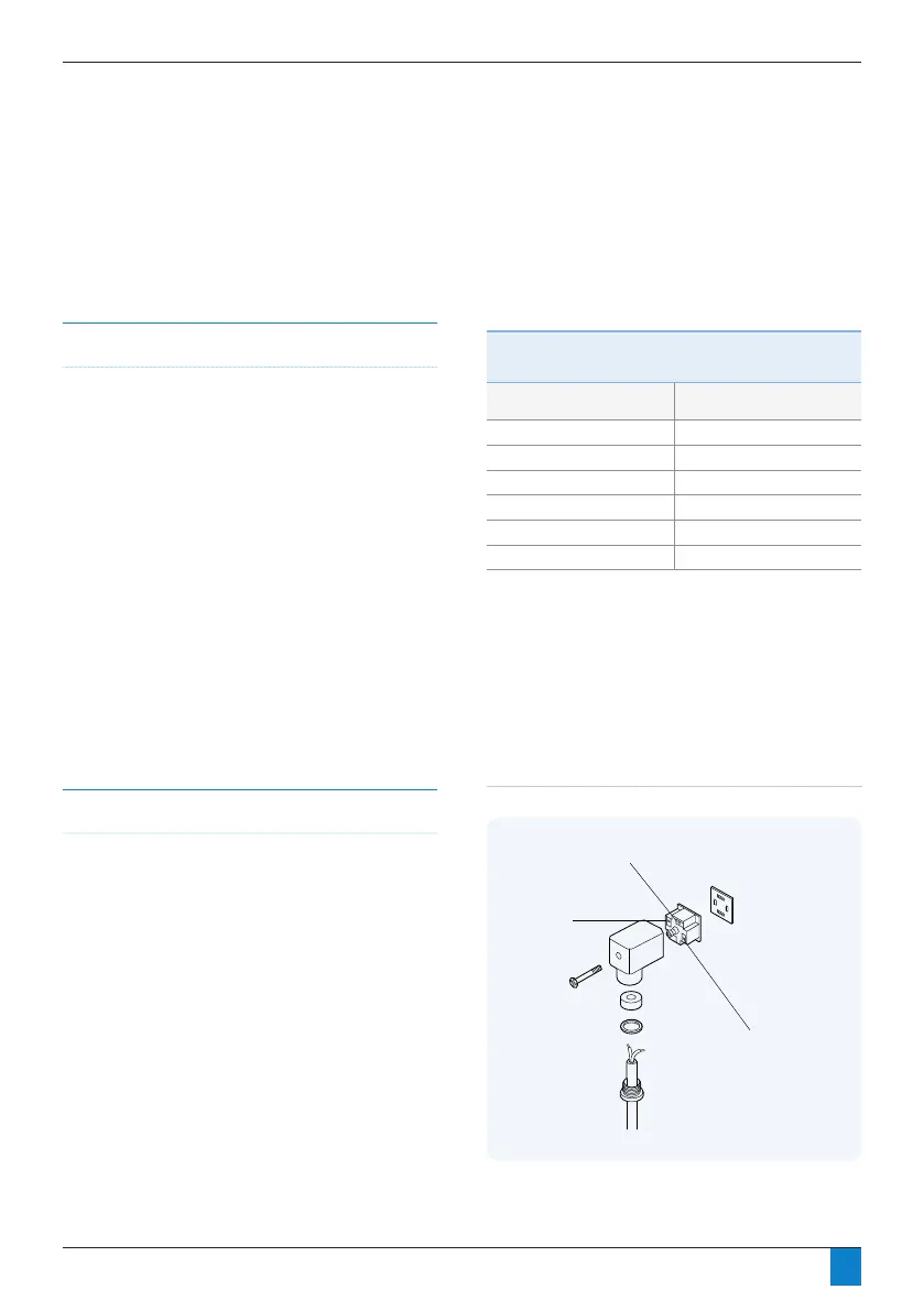
How to wire a power connector
Figure 4.1 illustrates how to wire power connector. Please
refer to wiring diagram, gure 4.2, page 17, for further
information.
1 (+)
LIVE
2 (-)
NEUTRAL
EARTH
GASKET
Figure 4.1: Din connector


 To Next Page