10
Assembly Instructions
INSTALLING A21 HI-DUMP
®
ON THE TRACTOR
1. Disconnect battery. Always disconnect the neg-
ative (-) terminal rst.
2. Unplug catcher harness at the rear of the
catcher box. Unbolt the gas spring at both
ends. Remove the catcher assembly—retain
the hardware, as it will be reused.
NOTE: If installing on tractor with Power Dump,
remove actuator, mount, electrical harness and
switch.
NOTE: This step will be more easily accom-
plished with the help of an assistant.
3. Remove the body chute from the tractor body.
Install the new (longer) body chute.
NOTE: If installed on a tractor equipped with a
10 in. blower, order body chute, P/N 8430. If
installed on a tractor equipped with a 10-1/2 in.
blower, use body chute 8430-1 (included).
NOTE: It may be necessary to enlarge the hole
in the body in order for the chute to t.
4. FOR LIQUID COOLED UNITS ONLY: Remove
the coolant recovery tank from the mount. Re-
move tank mount from the bumper—retain the
hardware, as it will be reused.
5. Remove rear bumper and discard—retain the
hardware, as it will be reused.
6. Remove the two (2) body bumpers mounted
on the back of the front body that the catcher
contacts when lowered. Install new bumper
(P/N 7847) on the right side, as shown in Install
Body Bumper photo.
Body Bumper
P/N 7847
Install Body Bumper
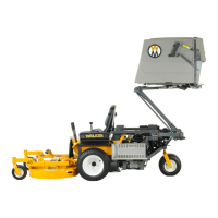
7. Unbolt the instrument panel from the chassis,
and remove the instrument panel guard—retain
all hardware, as it will be reused.
8. Remove the precleaner tube. Loosen hose
clamp and remove three (3) shock mount
nuts (two in front, one in rear); retain the
hardware, as it will be reused.
9. Remove the two (2) nuts that attach the pre-
cleaner tube support arm to the fuel tank
strap (chassis) and remove and discard the
precleaner tube support arm. Push bolts back
against the fuel tank but do not remove the bolts
or the PTO Blade Clutch Mount.
NOTE: For Model T25i only, remove two bolts
mounting fuel pump module on rear upright
bracket and stow pump assembly to the side.
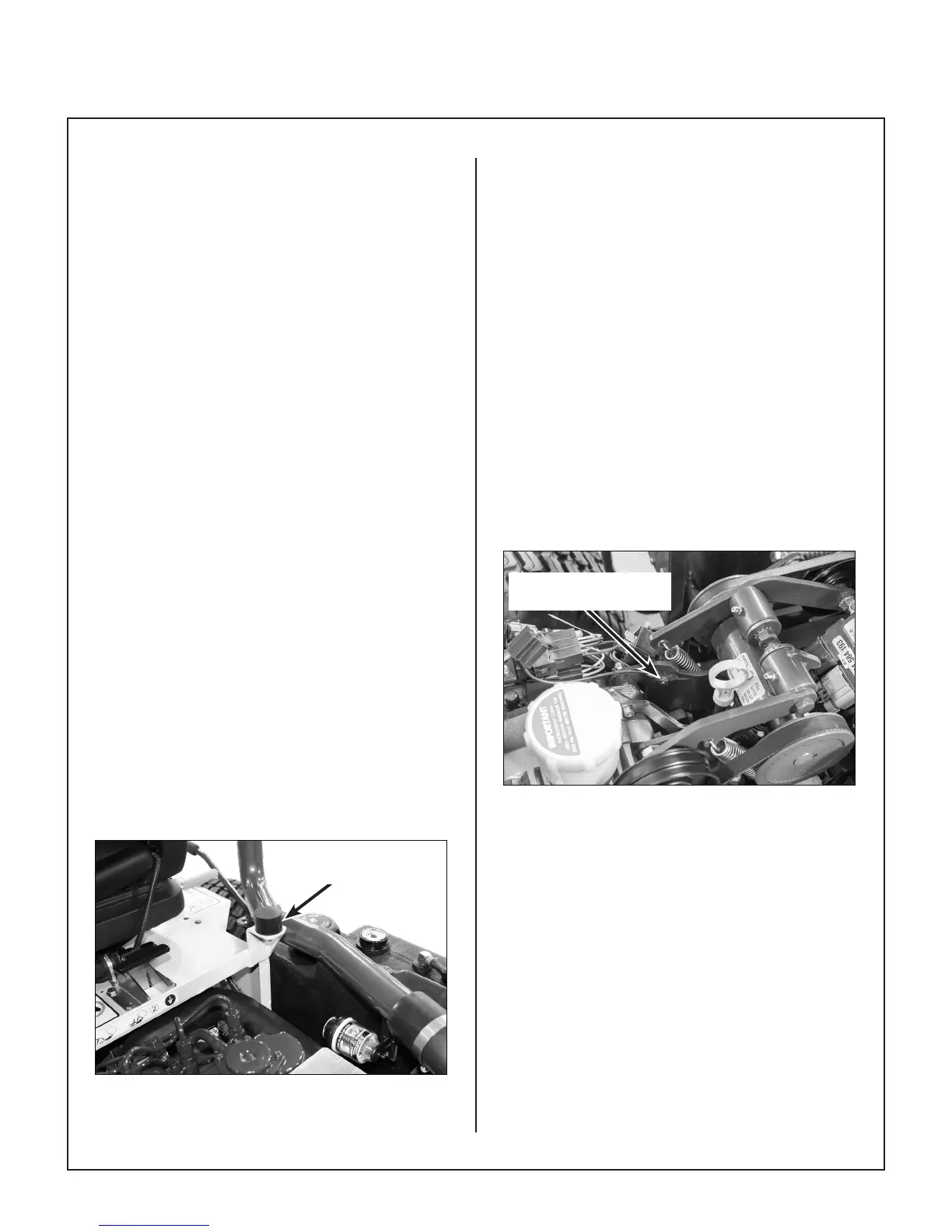
10. Grind paint around the hole in the jackshaft
mount to expose metal for ground (black wire)
as shown in Grind Paint on Jackshaft Mount
photo.
Grind Paint around Hole
on Jackshaft Mount
Grind Paint on Jackshaft Mount
11. FOR AIR-COOLED MODELS ONLY: Use a
pipe clamp to keep the chassis uprights from
spreading to ease installation, as shown in
Install Pipe Clamp to Keep Chassis from
Spreading photo.
(See photo on next page)