11
Assembly Instructions
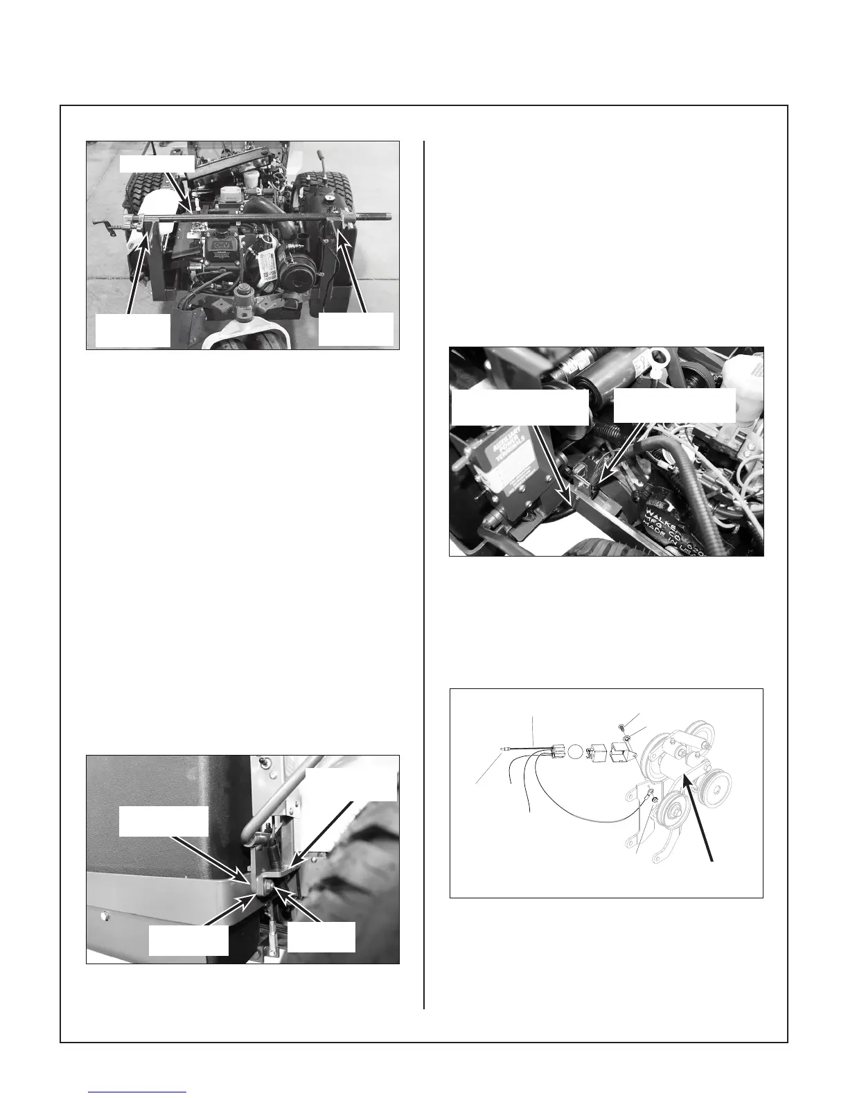
Pipe Clamp
LH Chassis
Upright
RH Chassis
Upright
Install Pipe Clamp to Keep Chassis Uprights
from Spreading
12. Carefully, set the Hi-Dump
®
assembly on the
chassis being careful not to knock the PTO
Blade Clutch Mount loose (off of the mounting
bolts, RH side). Make sure the Hi-Dump® wire
harness is not damaged as the assembly is
positioned on the chassis frame.
NOTE: This step will be more easily accom-
plished with the help of an assistant, or a well-
balanced lift/hoist.
13. If a pipe clamp was used, it can now be removed.
14. Using a at head screw driver, push the two
(2) bolts (partially removed in step 9) through
the fuel tank saddle and install the Hi-Dump
®
spacer (P/N 8400-77) over the bolts, then the
Hi-Dump
®
frame upright. Reinstall nuts, and
tighten securely, as shown in Install RH Hi-
Dump
®
Frame photo.
NOTE: The spacer (P/N 8400-77) is not used
on the MT30i.
PTO Blade
Clutch Mount
Spacer P/N
8400-77
Mounting
Bolt
Hi-Dump
Frame Upright
Install RH Hi-Dump
®
Frame
15. Route the harness under the chassis, and back
up in front of the PTO safety switch. Remove
and discard small cable clamp and replace with
larger clamp (P/N 5832). Install clamp using the
10-24 x 7/8 (F418) screw and the 10-24 (F002)
keps nut as shown in Install Cable Clamp to
PTO Safety Switch Mount photo being sure
to capture the PTO safety switch wires in the
cable clamp.
IMPORTANT: To avoid damage to the wire
harness, be sure the wire harness is pulled
snug under the chassis.
Wire Harness Routed
Under Chassis
Install Cable Clamp
P/N 5832
Install Cable Clamp to PTO Safety Switch Mount
16. Mount new relay switch (P/N 6941-8) and
bracket with one 10-24 x 1/2 (F026) screw,
one 1/4 star lock washer (F185), and one 10-
24 (F002) keps nut to the jackshaft mount as
shown in Install Relay Switch illustration.
To
Time Delay
Harness
G
F026
F185
F002
RED
Jackshaft
Assembly (Ref)
Install Relay Switch