21
Maintenance Instructions
ADJUSTMENTS
Catcher Box Clearance with Body Chute
● Using the LIFT switch, lower the catcher assem-
bly to the full down position. Check alignment of
the catcher box to the GHS body chute (blower
discharge chute). Make sure there is clearance
on all sides.
● To adjust clearance, loosen the bolts on both of
the catcher pivot plates (P/N 7517-3) and posi-
tion the catcher for proper clearnace with the
body chute. Re-tighten the pivot plate bolts.
Door Opening Cable Tension
● Tilt the catcher to the full back position using the
DUMP switch. Check the tension of both cables.
The tension should be equal. Adjust accordingly
with the ball joints. Tighten the jam nuts.
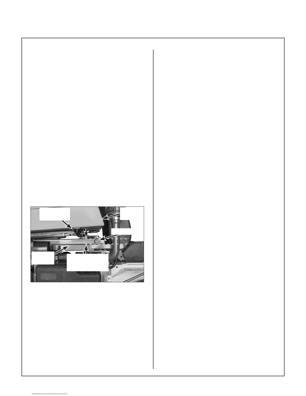
Control Lift Rod
● Check the lift operation of the Hi-Dump
®
. The
front pivot should lift approximately 1 in. (2.5
cm) before the rear starts to rise as shown in
Check Lift Operation photo. If this does not
occur the control rods will need to be adjusted.
Front Pivot Raises
1 in. Before Rear
Raises
Hi-Dump
Frame
Front Pivot
Catcher
Box
Catcher Box
Mount Frame
Check Lift Operation
NOTE: The control rods and ball joints have
RH and LH threads. They can be adjusted by
loosening the jam nuts and turning the rod.
If the front of the catcher raises more than 1 in.
(2.5 cm) before the back raises, shorten the
control rods. The rods need to be adjusted
equally. If the back of the box raises before
the front raises 1 in. (2.5 cm) or the back of the
box is slightly raised in the full down position
(not contacting the rear bumpers), lengthen the
control rods. The rods need to be adjusted
equally.