12
Assembly Instructions
17. Plug the wire harness into the relay and run
the Hi-Dump
®
harness along the tractor’s main
harness to the battery as shown in Route Wire
Harness photo. Use three 7 in. cable ties to
hold in place. Plug connector on relay harness
into connector on time delay harness.
NOTE: It is recommended to use dielectric
grease on the wire harness connectors to en-
sure a good connection, and to prevent dust
and moisture from entering the plugs.
Wire Harness
Route Wire Harness
18. Connect the battery cables and the Red (+) and
Black (-) leads of the Hi-Dump
®
to the battery.
Connect the Red (+) rst.
NOTE: Connect the positive (+) leads rst.
Install a 4 in. cable tie, on both battery terminal
insulators.
19. Clamp the left front Hi-Dump
®
mount (at the
instrument panel guard mount point) ush with
the chassis using a c-clamp as shown in Clamp
LH Front Hi-Dump
®
Mount photo. Install the
5/16-18 x 3/4 (F034) hex bolt and the 5/16-18
(F009) whiz locknut. Reinstall the instrument
panel and panel guard using existing hardware
removed earlier.
Clamp LH Front Hi-Dump
®
Mount
NOTE: If the Hi-Dump
®
mounting hole is not
present in the chassis, it will be necessary to
drill a 5/16 in. hole using the Hi-Dump
®
mount
as a guide. Install hardware through the Hi-
Dump
®
frame and tractor chassis and hand
tighten.
20. Turn the ignition switch to the ON (RUN) position
and use the LIFT control switch to raise the Hi-
Dump
®
to the full UP position.
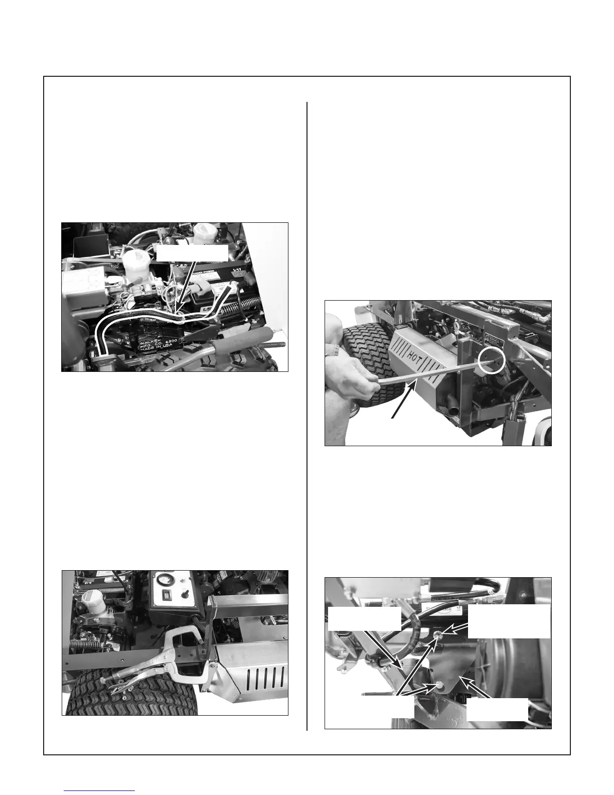
21. Using a tapered (drift) punch, align the left-rear
Hi-Dump
®
mounting holes to the chassis as
shown in Align Mounting Holes photo. Using
existing hardware, install bolt and nut in the
front hole and hand tighten. Remove punch and
install second nut and bolt. Leave bolts loose,
DO NOT tighten.
Tapered Punch
Align Mounting Holes
22. Using the tapered punch in the lower hole of
the rear upright mount in front of tailwheel pivot
housing, align the top hole as shown in Install
Hardware in Rear Upright Mount illustration
and install hardware.
IMPORTANT: To avoid damage, top bolt
(carriage head, F420) must be installed with
head towards hydraulic cylinder.
Carriage Bolt
Installed With Head
Toward Cylinder
Rear Upright
Mount Bolts
Rear Upright
Mount
Tail Wheel Pivot
Housing (Ref)
Install Hardware in Rear Upright Mount