13
Assembly Instructions
NOTE: If there is a gap between the rear
upright mount and the chassis frame, install the
optional shim (P/N 8400-39) for best t.
NOTE: For Model T25i only, reinstall the fuel
pump module at the same time.
23. Using the tapered punch align the front holes
of the right rear mount holes and install a bolt
(from the inside to outside) through the rear
precleaner mount, Hi-Dump
®
and chassis. Install
nut nger tight. Remove the tapered punch and
install a bolt (from outside to inside) through the
front mount holes of the chassis, Hi-Dump
®
and
rear precleaner mount and install nut nger tight
(using existing hardware removed earlier).
24. Using the tapered punch, align the holes where
the two (2) bumper upright supports connect
to the chassis and install existing hardware, as
shown in Align Bumper Upright Supports to
Chassis photo.
IMPORTANT: A production change was made
at tractor S/N 2018-151222, and A21 S/N 2018-
5402 that enlarged the hole from 3/8 in. to 7/16
in. It is possible that the Hi-Dump
®
kit bumper
and the tractor chassis could have differing hole
dimensions. If hole dimensions are different,
drill the smaller hole to 7/16 in.
Tapered Punch
Used to Align
Mount Hole
Bumper Upright
Support
Align Bumper Upright Supports to Chassis
25. Tighten all bolts and nuts.
26. Reinstall the precleaner tube and hose, using
existing hardware. Ensure hose clamps are
tight.
27. Lower the front body. Turn the ignition switch
to the ON (RUN) position and use the lift con-
trol switch to lower the Hi-Dump
®
to within
6-8 in. (15-20 cm) of the DOWN position.
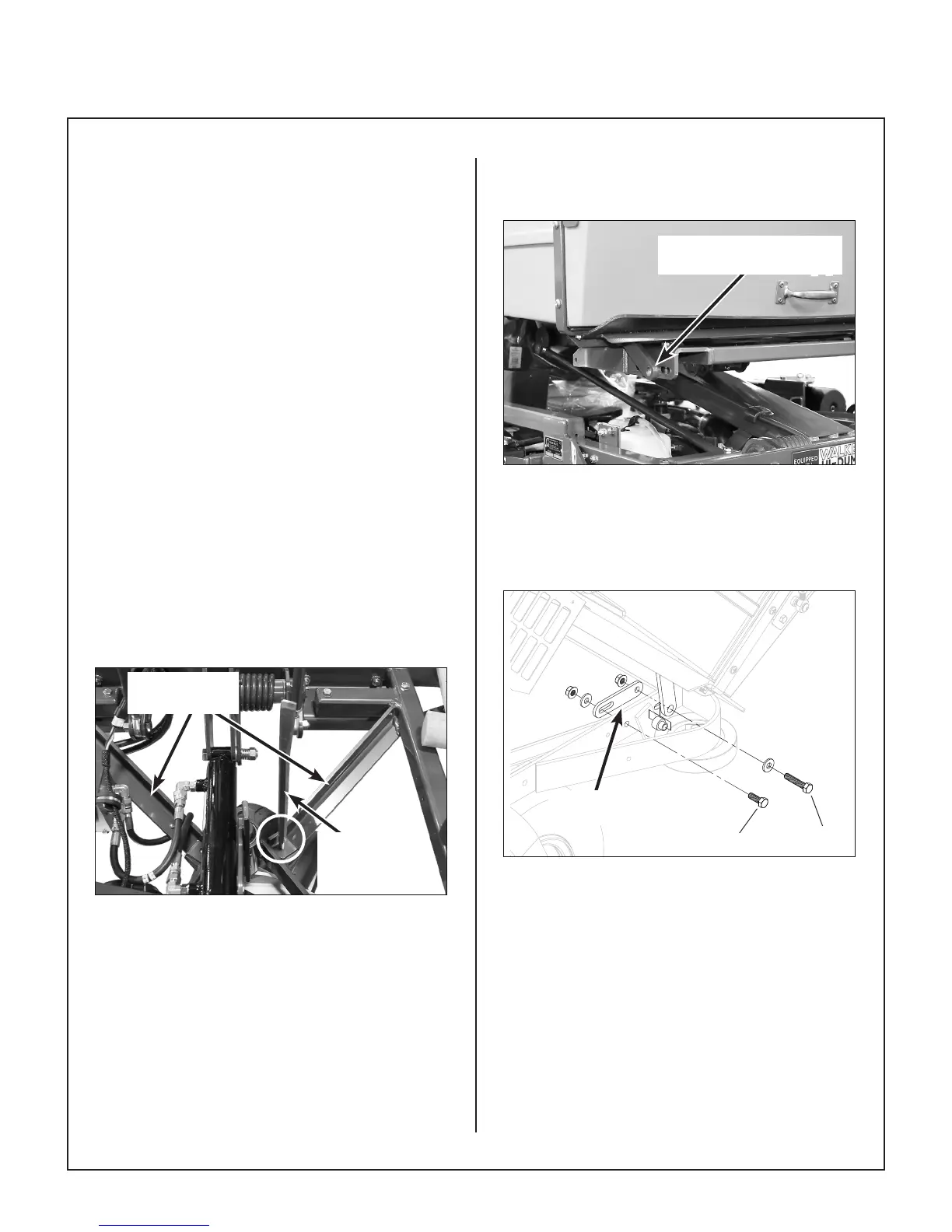
28. Place the catcher assembly on the Hi-Dump
®
frame as shown in Install Catcher Box As-
sembly photo.
Catcher Pivot Points
Outside Hi-Dump
®
Frame
Install Catcher Box Assembly
29. Install the two (2) new catcher pivot plates (P/N
7517-3), as shown in Install Catcher Pivot
Plates illustration. Hand tighten the bolts and
nuts reusing existing hardware.
F038
Catcher Pivot
Plate
F041
Install Catcher Pivot Plates
30. Using the LIFT switch, lower the assembly to
the full down position. Align the catcher box to
the GHS body chute (blower discharge chute).
Make sure there is clearance on all sides.
Tighten the catcher pivot plate hardware in-
stalled in the previous step.
31. Attach the RH and LH channel angles (P/N
8404-12 and 8404-13) to the catcher frame
support with the two (2) 1/4-20 x 1/2 (F029)
hex bolts and two (2) 1/4-20 (F004) keps nuts
attaching the front of the channel nger tight.