14
Assembly Instructions
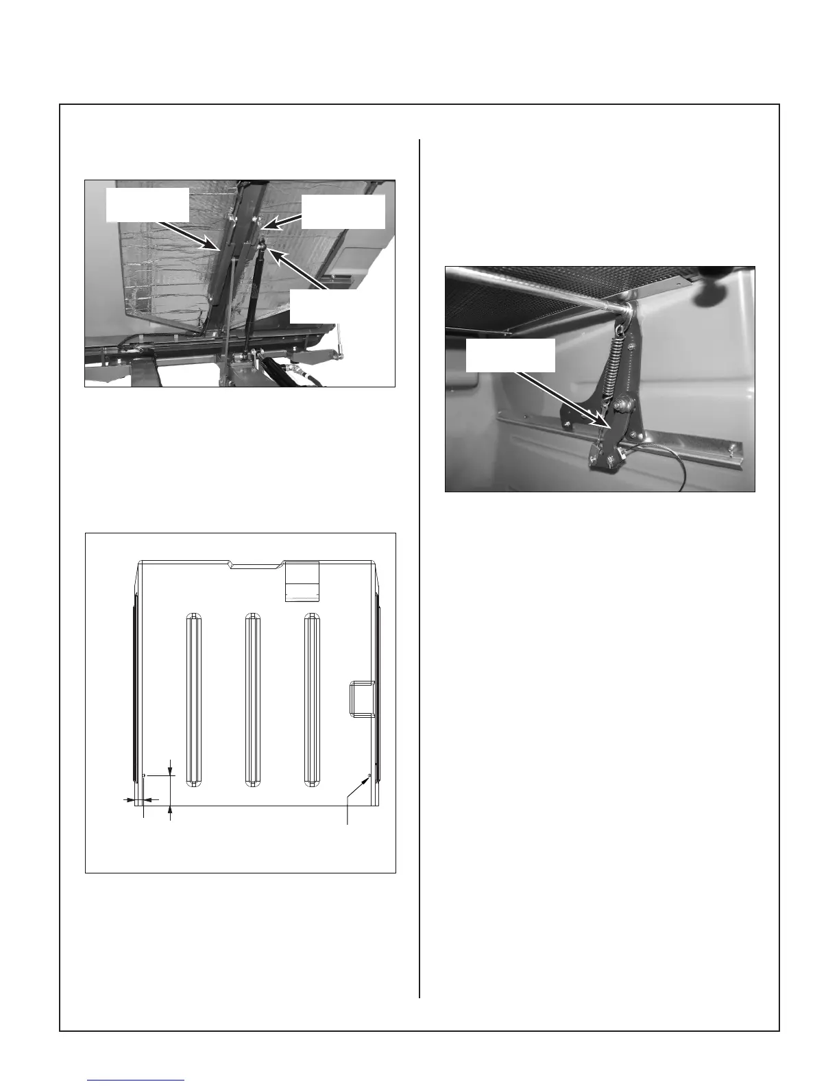
NOTE: The channel angle with the ball stud
mount attaches to the left side.
RH Channel
Angle
LH Channel
Angle
Ball Stud on
Channel Angle
Install Power Dump Arm Channel Angles
32. For installing the power dump cables (P/N
8623-2), drill two (2) 3/8 in. holes approximately
1/4 in. inside the radius of the catcher box
and 4 in. from the opening of the catcher box
as shown in Drilling Dimensions for Power
Dump Cables photo.
* Typical Two Places
DRILL 3/8
"
DIA. THRU. TYP .2
1/4" TYP .2
4" TYP .2
FRONT OF CATCHER BOX
VIEW FROM BOTTOM OF CATCHER BOX
REAR OF CATCHER BOX
1/4 in.*
4 in.*
Drill 3/8 in Dia.
Hole*
Rear of Catcher Box
View from Bottom of Catcher Box
Front of Catcher Box
Drilling Dimensions for Power Dump Cables
33. Remove the cotter pins on both ends of the
torsion bar (inside catcher box). Insert spring
hook ends on both ends of torsion bar and
reinstall bar with new cotter pins.
34. Remove existing lower arms (outside of catcher
box) and install new Lower Power Dump Arms
(P/N 8607-10) on both sides.
35. Install new inner power dump arms (P/N
8623-6 RH and P/N 8623-7 LH) on both sides
and orient each one as shown in Inner Power
Dump Arm photo.
Inner Power
Dump Arm
Install Inner Power Dump Arm
36. Assemble door springs to spring hooks (att-
ached to torsion bar) and attach extension
spring clevis end to inner power dump arm, as
shown in Assemble Door Springs to Spring
Hooks and Attach Extension Spring Clevis
illustration.
(See next page)