15
Assembly Instructions
P/N 8608-9
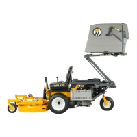
Torsion Bar
Spring Hook
on Torsion Bar
Lower Arm
Cable Guide
Cable
Assembly
Ball Joint
Hole in
Catcher Box
Hi-Dump
®
Frame
Extension
Spring Cable
Inner Power
Dump Arm
Assemble Door Springs to Spring Hooks and
Attach Extension Spring Clevis
37. Attach cable assembly to inner power dump
arms with clevis pin, as shown in Assemble
Door Springs to Spring Hooks and Attach
Extension Spring Clevis illustration. Install
threaded end of cable assembly through each
hole. Attach ball joints to cable ends. Attach
ball joints to Hi-Dump
®
frame bracket.
38. Tilt the catcher to the full back position using
the DUMP switch. Check the tension of both
cables. The tension should be equal. Adjust
accordingly with the ball joints. Tighten the jam
nuts.
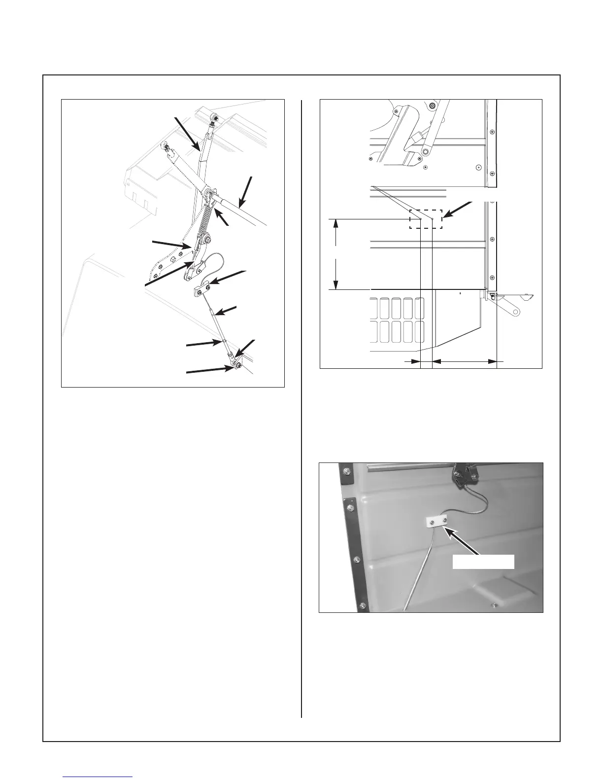
39. Drill holes in both sides of the catcher box
(as shown in Drilling Dimensions for Cable
Guide Installation) to install cable guides (P/N
7620-6) inside catcher.
7 1/2”1 5/16”
DRILL 3/16” DIA.
HOLES
8”
Drill 3/16 in.
Holes
1-5/16 in.
7-1/2 in.
8 in.
Cable Guide
Drilling Dimensions for Cable Guide Installation
40. Install guides on both sides, using the two (2)
10-24 x 3/4 (F028) screws, two (2) 3/16 Rivet
Backup Washer (F085), and two (2) 10-24
(F002) keps nuts as shown in Install Cable
Guides photo.
Cable Guide
Install Cable Guides
41. Plug the grass catcher harness into the main
harness. With the ignition switch in the ON
(RUN) position and the PTO engaged, check
the operation of the Powerl
®
.