16
Assembly Instructions
NOTE: Check that the spout is oscillating and
the Grass-Pak
®
switch triggers the Full Signal
Horn to sound when the vane is pushed toward
the LH direction while oscillating.
42. FOR LIQUID-COOLED MODELS ONLY:
Remount the coolant recovery tank using the
new mount plate and hardware provided. Tie
the hose to the frame using two 7 in. cable ties.
Make sure the cable ties are not so tight as to
restrict coolant from owing through the hose.
NOTE: It may be necessary to shorten the
recovery tank hose by approximately 3 in. (7.6
cm)
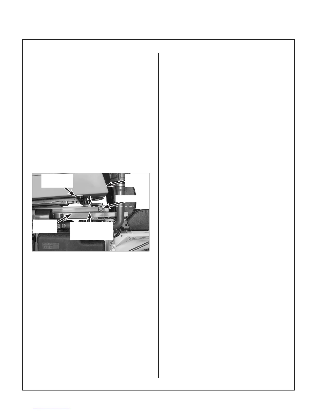
43. Check the lift operation of the Hi-Dump
®
. The
front pivot should lift approximately 1 in. (2.5
cm) before the rear starts to rise as shown in
Check Lift Operation photo. If this does not
occur the control rods will need to be adjusted.
Front Pivot Raises
1 in. Before Rear
Raises
Hi-Dump
Frame
Front Pivot
Catcher
Box
Catcher Box
Mount Frame
Check Lift Operation
NOTE: The control rods and ball joints have
RH and LH threads. They can be adjusted by
loosening the jam nuts and turning the rod.
If the front of the catcher raises more than 1 in.
(2.5 cm) before the back raises, shorten the
control rods. The rods need to be adjusted
equally. If the back of the box raises before
the front raises 1 in. (2.5 cm) or the back of the
box is slightly raised in the full down position
(not contacting the rear bumpers), lengthen the
control rods. The rods need to be adjusted
equally.
44. Use the LIFT and DUMP control switches to
make sure the system operates properly.