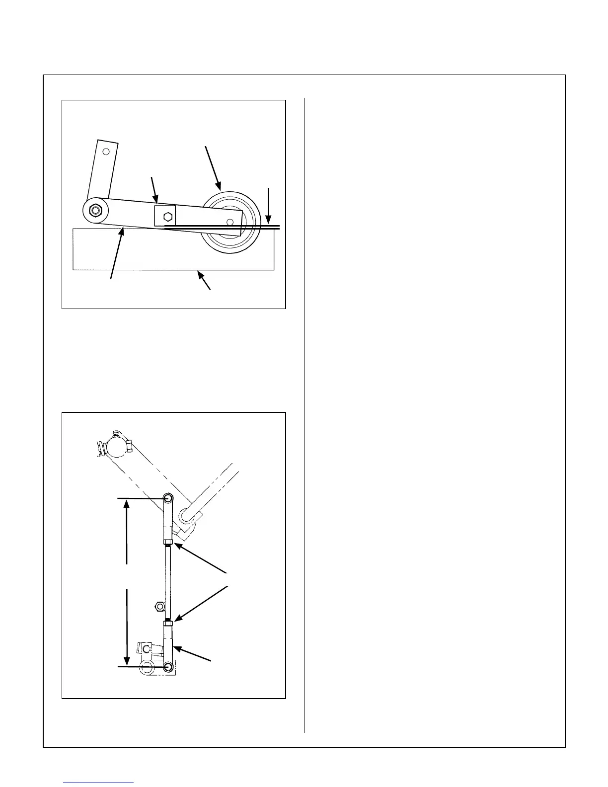
Blade Brake Band Adjustment
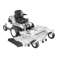
NOTE: The length of the actuator rod is adjusted
by disconnecting the bottom clevis and shortening
or lengthening accordingly. The standard pre-set
length of the actuator rod is set at the factory at
8-1/4 in. (209 mm).
Brake Actuator Rod Adjustment
2. After adjustments are complete, check blade
brake action as described in CHECKING/SER-
VICING the Blade Brake Action in this section.
If blades do not stop within five (5) seconds,
check the following:
a. Recheck 1/8 in. (3 mm) gap between stop
block and chassis.
b. Make sure clutch and brake linkage are
working freely (no binding).
c. Check the brake band lining.
d. Check the brake drum on the pulley. If
excessive wear is present, it will be neces-
sary to replace worn parts.
Transmission Control
IMPORTANT: The proper adjustment of the trans-
mission control stops is essential for efficient oper-
ation and life of the transmission. These stops are
properly adjusted at the factory and should only re-
quire readjustment if the transmission or related
control linkage is removed or changed.
NOTE: It would not be unusual for a new machine,
after initial 5 or 10 hours of operation, to begin to not
travel straight (this is due to the break-in of the
transmissions). In this case, proceed to
Straight
Ground Travel Adjustment - Step 4
.
IMPORTANT: The following adjustment proce-
dures are sequential. Check and adjust each func-
tion in the order given.
Set Forward Travel Limit (Stop) - Step 1
1. Move the Forward Speed Control (FSC) lever to
the most FORWARD position.
2. Check clearance of the RH and LH steering le-
ver actuator arms with the frame and adjust for-
ward stop bolt so each lever clears the frame
by at least 1/16 in. (1.6 mm). Clearance of the
arm to the frame should be checked while ap-
plying pressure back on the arm to remove
any slack in the linkage.
Blade Clutch
Idler Pulley
1/8 in.
(3 mm)
PTO Belt Tightener
Chassis
Stop Block
8-1/4 in.
(209 mm)
Bottom
Clevis
Locknuts