5.0 INSTALLATION AND FIXING
2
EXT.SBB-HFF.--.M.A.0219.EN Issue: A
02.19
27
SBB-HFF
(ONLY MODEL S)
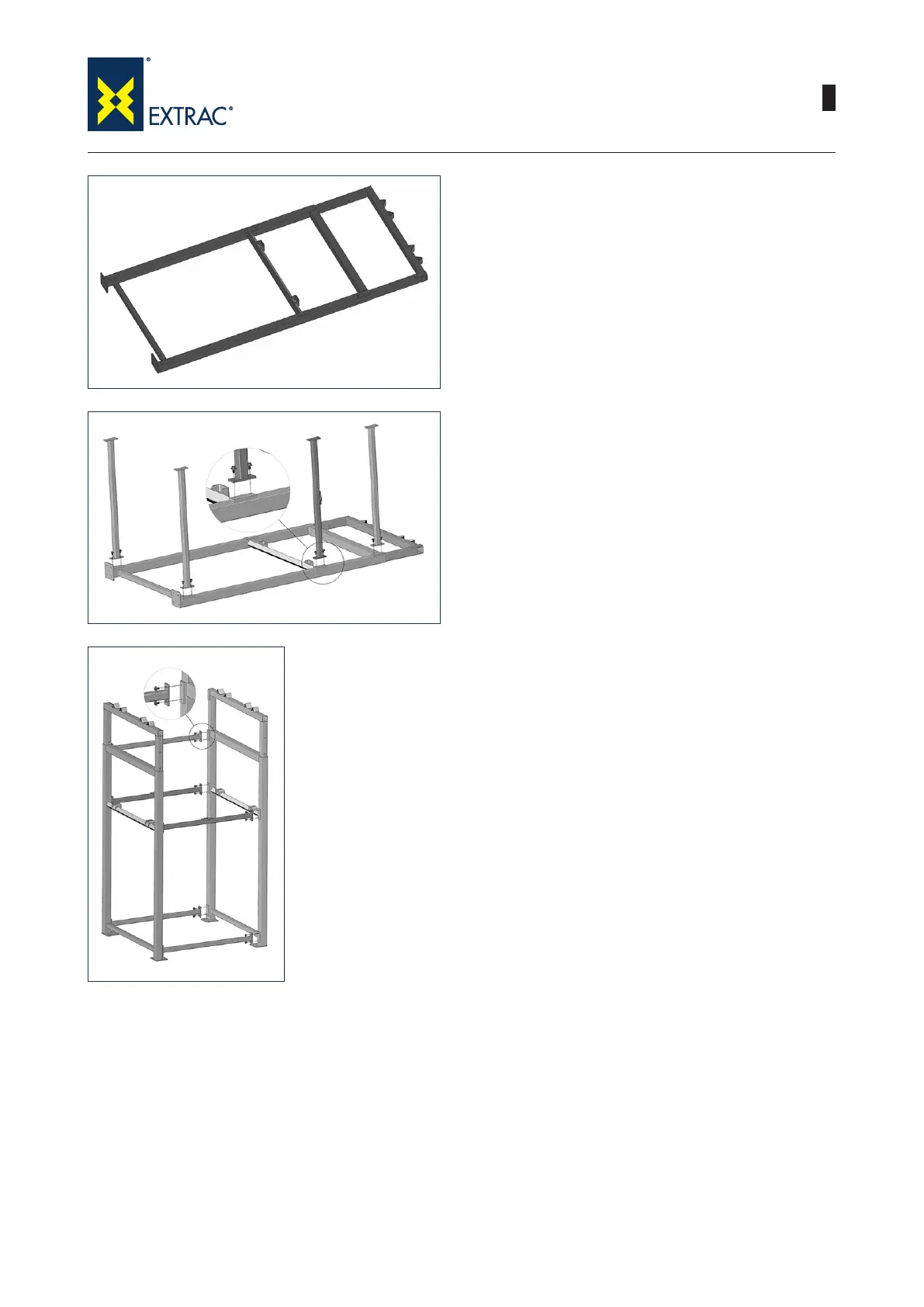
4) Start assembling the frame by inserting each
of the two removable parts within the respec-
tive xed part of the frame; Pay attention to the
direction of insertion: the anges used to join
the cross beams on the removable and xed
part must be on the same side as shown in the
gure.
5) Proceed by connecting the rst 4 cross beams
to the xed part of the frame. For the moment,
do not tighten the screws until they cannot be
tightened further but leave a clearance of ap-
proximately 4-5 mm.
Use a torque wrench to ensure the following tight-
ening torques:
M16 screws: 225 Nm
M18 screws: 439 Nm
6) Lift the frame upright as shown and push the
other side.
Use a torque wrench to ensure the following tight-
ening torques:
M16 screws: 225 Nm
M18 screws: 439 Nm