22
SECTION 4.0 - Control Pack Overview And
Wiring Reference
Electrical operation of the winch control may consist of a dial control switch, a
power in/ power out contactor or a set of two solenoids.
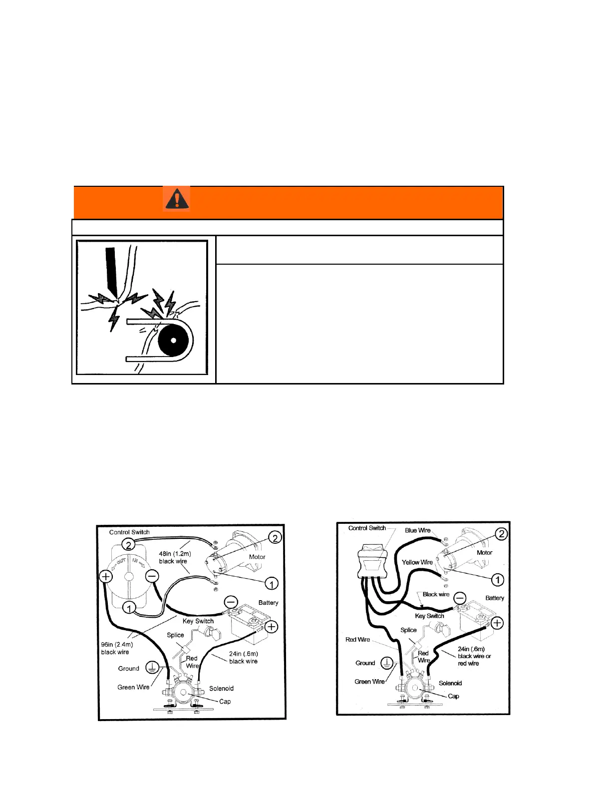
Failure to observe these instructions could
lead to severe injury or death.
--Never route electrical cables:
- Across any sharp edges.
- Through or near moving parts.
- Near parts that become hot.
--Always insulate and protect all
Exposed wiring and electrical terminals.
--Always install terminal boots as
directed in installation instructions.
4.1 Overview Of Control Operation
4.1.1 Dial Control Switch- This switch is wired between the battery and
the winch through a power interrupt solenoid. The switch must be wired properly. Improper
installation may result in permanent damage to the control switch. Insure that the control switch
is wired to the appropriate terminals.
Figure 4.1a is the basic wiring diagram of the ATV winch dial control switch.
Figure 4.1b is the basic wiring diagram of the ATV winch rocker control switch.