Assembly and Parts, Cont.
Injector Assembly
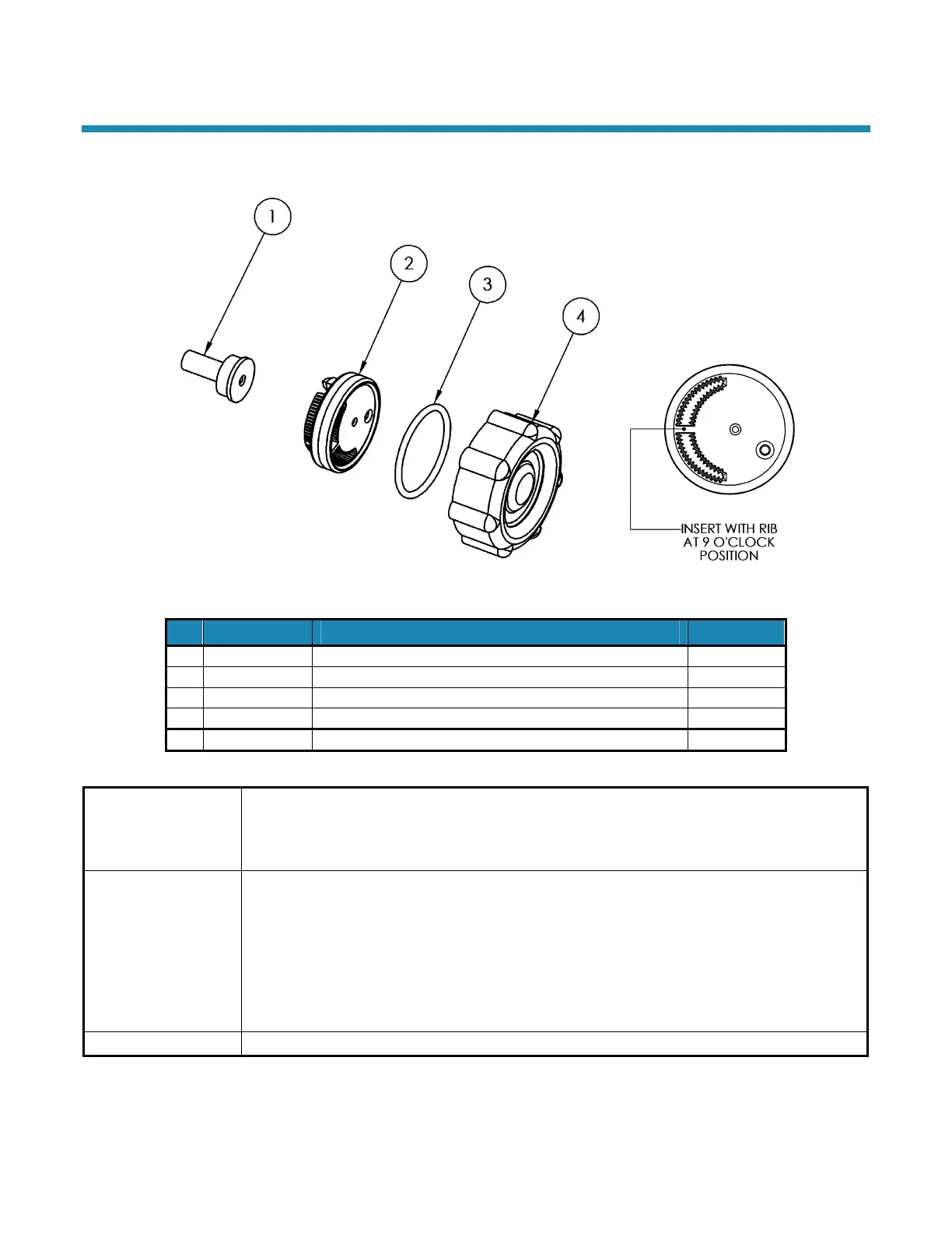
Figure 15: Injector Assembly
Part # Description Quantity
1 93223 Injector Throat 1
2 53224 Injector Nozzle with Over-Mold Gasket 1
3 93806 O-Ring 1
4 53235 Injector Cap 1
93504 All of the above parts
93223 Injector
Throat
In conjunction with the Injector Nozzle (53224) it creates the vacuum that draws the brine solution
from the brine cabinet. The center hole should be clear of debris, round, and undamaged. The
Throat should be pressed flush into the opening in the valve. If the Throat is removed, it must be
replaced with a new one.
53224 Injector
Nozzle with
Over-Mold Gasket
Together with the Throat (93223) creates the vacuum that draws the brine solution from the Brine
Cabinet. The small hole in the Injector Nozzle (53224) is the one that creates the
“injection-stream” that enters the Throat. It is important that this hole is round, undamaged, and
clear of debris. If this hole becomes “clogged,” do not use anything (such as metal objects) to
clear this opening. Damage may occur. Use a clean cloth and flush with water. If necessary, a
wooden toothpick may be used. When assembling to the Valve, the Nozzle hole should line up
with the Throat. Flush screen with water to clean. The over-mold gasket seals between the
Injector Nozzle and the Injector Cap.
53235 Injector Cap Holds the injector assembly together and seals the assembly to the Main Valve Body.
WaterBoss Softener Owner’s Manual 12/2/2010 23
 Loading...