Step 2: Connect the water supply (cold water only)
1. Shut o the water supply. Remove the faucet hose. (Figure 1)
2. Connect the inlet hose to the cold water valve.
• If the angle valve outlet is 3/8”, it can be directly connected to the water supply. (Figure 3)
• If the angle valve outlet is 1/2”, connect it with a No.1 converter at rst. (Figure 4)
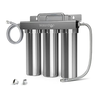
Triple-Stage Undersink Water Filtration System
WD-TSA-10 system | Installation Instructions
Note: The service life mentioned above is subject to chlorine reduction. Actual result varies according
to the local water quality.
Precautions
• Do not use it with water that’s microbiologically unsafe or of unknown quality without adequate disinfection.
• For use only with cold water.
• Do not freeze the lter, as this can cause cracking and water leakage.
• Do not allow children under 3 years old to have access to small parts during installation of this product.
• This installation must comply with all applicable state and local regulations.
• Turn o the water supply while replacing the lter.
Inlet hose
Outlet hose
Teflon tape
Filter head
3/8”-1/2” converter
Operating temperature
Working pressure
Flow rate
Filter capacity
2-38℃/35-100℉
10-125psi (0.7-8.6bar)
1gpm
Specifications
Feed water requirement Municipal tap water
WD-10PP: up to 6 months
WD-10GC: up to 8-12 months
WD-10CT: up to 12-18 months
Figure 3 Figure 4
3/8” outlet
1/2” outlet
Connect
①
to the cold angle valve
①
WARNING
Please read it carefully before installation.
Step 3: Connect to the faucet
1. If the angle valve outlet is 3/8”, it can be directly connected to the water supply. (Figure 5)
2. If the angle valve outlet is 1/2”, connect it with a No.2 converter at rst. (Figure 6)
Figure 5 Figure 6
②
Faucet hose
Outlet hose
Faucet hose
Note: If a female threaded connector is needed, please contact our service team for help.
Step 4: Connect to the filter system
Connect the inlet hose and the outlet hose to the lter head. Make sure the hoses hit the bottom of
the lter head.
Note: When the hose is tightly inserted, there will be a 1/8 inch gap between the hose and the lter
head, which is designed for easy replacement and won't aect the sealing performance.
Step 5: Flush the filter and check the leaks
1. Flush the lter for 5 minutes before use.
2. If water leakage occurs, turn o the water supply. If the water leakage is occurring at position 1 and 2,
wrap Teon tape on the external thread. If the water leakage is occurring at position 3 or 4, insert the
quick-connect tting to the end and make sure the hoses hit the bottom of the tting.
Inlet hose
ColdHot
Outlet hose
Filter system
Faucet hose
1
2
3 4
Figure 1
Inlet hose outlet hose
Installation of the filter system
Tips: How to disconnect the quick-connect?
Use your thumb and index nger to press down on the lock sleeve. Use your other hand to pull out the
hose from the tting.
Note: Please do not pull out the tubing directly, or else it will damage the tting and cause leakage.
Step 1: Fix the filter head and the filter
1. Paste the assistant label to nish drilling.
Note: Mount the water lter at least 2 inches higher
than the ground for easier lter change.
2. Install the screw and reserve enough space to hang the lter.
3. Hang the lter system on the screw.
Press
Pull
Press