5. COLD WATER SUPPLY
DO NOT CONNECT DIRECTLY TO WATER MAINS SUPPLY
DO NOT USE ANY JOINTING COMPOUNDS
The cold water supply to the pump must be connected using 22mm pipe, to the cold water
tank (do not connect to the central heating header tank!) see Fig 1. The tank connector
should be positioned at least 25mm (1”) lower than the cold water feed to the hot water
cylinder, to prevent the supply of hot water only.
6. CONNECTING PUMP
DO NOT USE ANY JOINTING COMPOUNDS
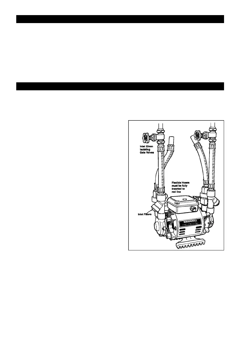
For ease of installation, future servicing and cleaning of filters, full bore isolating gate
valves should be fitted in both hot and cold inlets and outlets.
Isolating valves greatly assist draining down,
filter cleaning and refilling, which will result in
much lower service costs.
The flexible hoses supplied with the pump, or
authorised replacements from Watermill, must
be used for connecting this pump to the
pipework. Use of these hoses will ensure strain
and vibration-free watertight connections.
Make sure each hose connection is fully
inserted to the red “insert guide line”. When
connecting to the pump hoses, make sure
connecting pipe is fully inserted to a minimum
depth of 33mm (1
1
/4”). Failure to fully insert
connections will cause leaks
The inlets to the pump are fitted with strainers
to prevent damage to the pump from abrasive
debris in the water supply.
After initial installation, run the pump for a few
minutes, switch off, drain down and clean the
strainers.
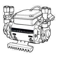
If Y strainers are fitted (as fig. 2) access is via the angled plug on the inlet port. If internal
strainers are used remove the inlet hose from the pump and the strainer basket can be
removed by hand or with long nosed pliers.
Position pump level (see section 3 positioning pump) ensuring that the outlets are vertical
for correct operation of the flow switches.
Line up pipework and fit hoses to pump before connecting to pipes. Position pipework
accurately sop that the pump is not subject to mechanical strain, such as supporting
weight of pipes.
Do not bend hoses as this will cause restriction of flow.
Figure 2
4