8
Installation
- Drain Line Connection -
1. The drain line ow control assembly is pre-assembled for your convenience. Should you choose to hard
plumb the drain line, please remove the barb tting. The ow control housing can be removed by remov
ing the clip and pulling straight out on housing.
Note: When re-installing the drain line ow control housing, be sure you hear and feel the O-Ring pop into
place before inserting the clip.
2. Install 1/2” I.D. drain line tubing (not included) from hose barb to an open drain. A 4” gap between end of
the drain line and the open drain is required to prevent waste water backow. Keep the drain line as
short as possible. An overhead drain line can be used if necessary, but should discharge below the con
trol valve. A syphon trap (taped loop) at the outlet of the drain line is advisable to keep the drain line full
and assure correct ow during backwash. Elbows or other ttings must be kept at a bare minimum.
Note: Where the drain line is elevated above the control valve or exceeds 20 feet in length, 3/4” I.D. drain
line tubing should be used.
-Brine Line and Overow Connection-
Note: Your brine tank comes with two brine lines. Black is for outdoor installation. Opaque is for indoor installation.
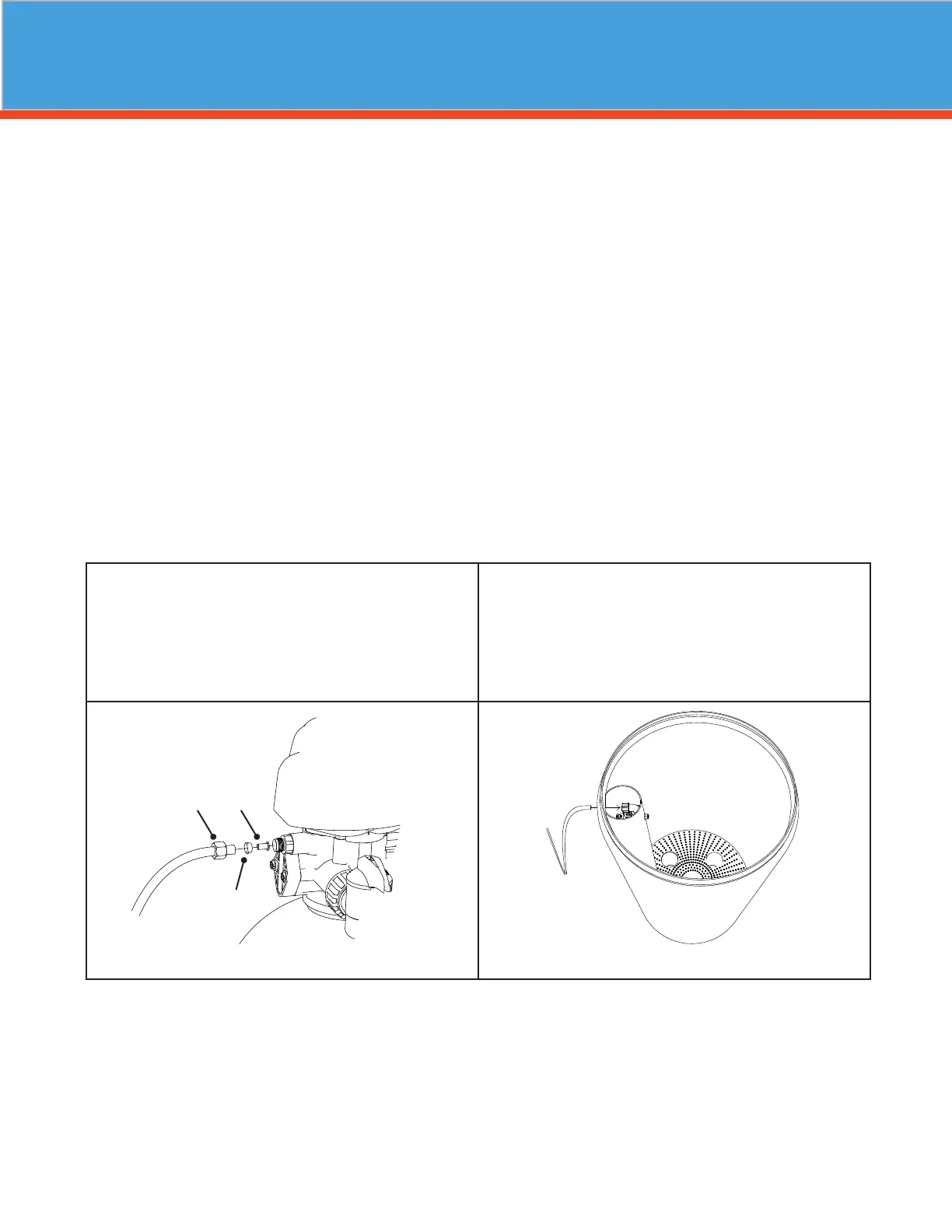
Remove brass compression nut from the softener con-
trol valve. Take brine tubing (packaged with brine tank)
and slide the brass nut and plastic ferrule onto one end
of the tubing. Find the plastic tubing insert (taped to the
brine well cap inside the brine tank) and insert it into the
end of the tubing. Next, insert the tubing into the control
valve and tighten the nut.
Inside the brine tank, remove the cap from the top of the brine
well. Feed the other end of the brine tubing through the hole
in the side of the brine tank, and firmly insert it all the way into
the push-lock elbow fitting inside the brine well. When this
tubing is fully inserted, the fitting will grab the tubing and hold
it in place.
BRINE LINE CONNECTION TO CONTROL VALVE
BRINE LINE CONNECTION TO BRINE TANK
Insert
Nut
Ferrule