4
Installation
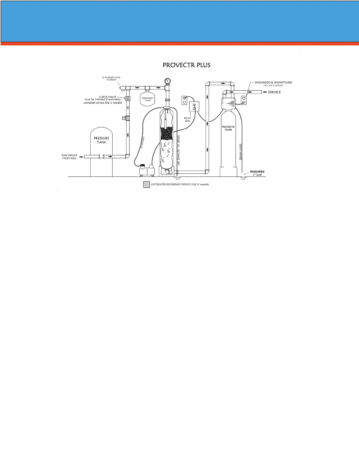
-Installation Requirements-
A/P Tank
• A level oor position between the well pump and pressure tank. (See Typical Installation Diagram.)
• DO NOT install in an area of direct sunlight or where freezing temperatures may occur!
Filter Tank
• A level oor position ahead of piping into water heater.
• Unit must be installed at least 10’ ahead of the inlet to a water heater to prevent damage due to back-up
of hot water.
• DO NOT install the unit in an area of direct sunlight or where freezing temperatures may occur! (See Typi
cal Installation Diagram.)
Relay Box
• Locate relay box near the lter tank and an unswitched 120v / 60 Hz grounded outlet
• You will notice an 8 foot meter cord and plug attached.
Note: If household plumbing is galvanized and you intend to make an installation with copper or vice ver-
sa, obtain dielectric unions to prevent dissimilar metal corrosion.
Where the drain line is elevated above the control valve or exceeds 20 ft. in length to reach the drain,
use 3/4 in. I.D. drain line tubing instead of 1/2 in.
When sweat soldering copper pipe, remember to always use lead free solder and ux. Cover yoke and
bypass valve with wet rags to prevent heat damage to connections and control valve. If using PVC or
plastic pipe, primers and solvent cements specically recommended for use for potable water are
required.
Always Follow Local Plumbing Codes.
• All plumbing lines not requiring treated water should be connected upstream of the Provectr Plus tank.
PROVECTR
FILTER
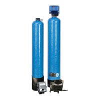
PROVECTR PLUS
 Loading...