5
-PROVECTR Plus Location / Other Requirements-
• Locate the lter near a 120 volt / 60 Hz grounded electrical outlet.
• Check for distance and proper drain installation (e.g. oor drain, washing machine standpipe).
• Determine type and size of piping required for PROVECTR connection (e.g. galvanized, PVC plastic).
Note: If household plumbing is galvanized and you intend to make an installation with copper (or vice ver
sa), obtain di-electric unions to prevent dissimilar metal corrosion.
Note: Where the drain line is elevated above the control valve or exceeds 20' in length to reach the drain,
use 3/4" I.D. drain line tubing instead of 1/2" I.D. Drain line tubing is not included.
Caution: When sweat soldering copper pipe (remember to always use lead free solder and ux), bypass
valve with wet rags to prevent heat damage to connections and control valve! If using PVC or plas
tic pipe, primers and solvent cements specically recommended for use with potable water are
required.
Note: All plumbing lines not requiring “ltered” water should be connected “upstream” of the A/P Tank.
(See Typical Installation Diagram.)
-Installation Procedure-
Caution: Raised arrows located on the sides of control valve body and bypass valve indicate proper direc
tion of water ow. Install inlet and outlet piping in direction of arrows. It is recommended that a
vacuum breaker be installed on the inlet plumbing.
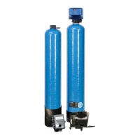
1. Position AP tank and Filter tank at the desired location. The AP tank must be installed between the
pump/pressure tank and lter tank. If a water softener is to be installed, it should be positioned after the
lter tank.
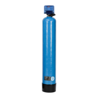
2. The lter media is shipped separately from the lter tank and should be loaded prior to installation.
a) Remove control valve by unscrewing it from the lter tank.
b) Plug distributor with cap provided to prevent any media from entering the inside of the tube.
c) Place media funnel onto tank and ll tank 1/3 with water
d) Pour in media. Never ll tank more than 2/3 full to allow room for backwash. Since the Provectr
comes with a Vortech tank, gravel is NOT needed.
e) Remove cap and replace control valve.
3. Turn o main water supply and open nearest faucet to relieve pressure.
4. Cut main line and install the AP tank and Filter tank.
5. Turn on main water supply and allow water to ow through new plumbing and keep the nearest faucet
open to evacuate air.
6. Check for leaks.
7. If no leaks, proceed by slowly opening the bypass and allow water to ll the lter tank.
8. Allow water to run through the lter for a few minutes and then turn o the nearest faucet.
Installation
 Loading...