6
- Water Supply Connection and Bypass Valve -
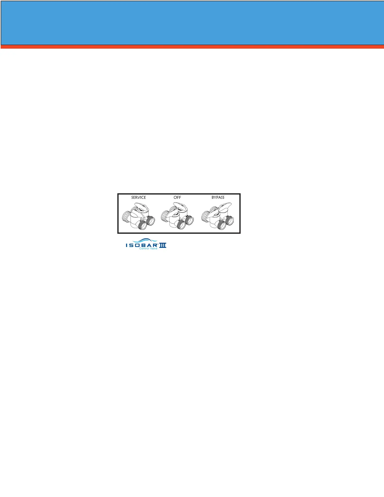
To allow for servicing, swimming pool lling or lawn sprinkling, a manual Bypass Valve has been installed at
the factory. The Bypass allows raw water to be manually routed around the lter.
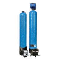
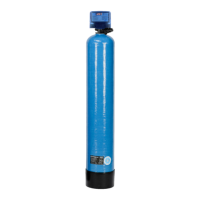
1. Position the A/P Tank and Filter Tank at desired location for installation. The lter tank must be installed
after the pressure tank. (See Installation Diagram.) If a water softener is to be installed, it should be posi
tioned after the lter tank.
2. The lter material is shipped separately from the Filter Tank. The Filter Tank must be loaded with material
after tank has been placed at the desired location.
A. Remove the control valve by unscrewing from the tank.
B. Use cap provided to place over top of distributor tube to prevent media from entering tube while
lling.
C. Place media funnel in hole on top of tank.
D. Pour several gallons of water in the tank. (Fill tank about 1/3 full.)
E. “D” gravel underbidding is not needed.
F. Pour in desired media to the correct level.
Note: 1/3 of the tank should be empty (Freeboard).
G. After lling the tank with media, ll the tank completely with water.
Note: This will permit the ltering material to become soaked while preparing the installation and will pre
vent the control valve from being plugged with oating material on initial backwash.
H. Remove funnel and clean lter material from tank threads.
I. Remove cap from distributor tube.
J. Replace control valve on mineral tank.
Caution: Be extremely careful to position distributor tube into control valve distributor tube pilot hole.
3. Turn OFF main water supply and OPEN nearest faucet to relieve pressure.
4. Cut main line and install appropriate elbows and extensions. Inlet connection on the A/P Tank is 1" FNPT.
The outlet is 1" MPT. Inlet is in the top of the tank and outlet is out the bottom.
Caution: Raised arrows located on the sides of control valve body and bypass valve indicate proper direc
tion of water ow. Install inlet and outlet piping in direction of arrows. It is recommended that a
vacuum breaker be installed on the inlet plumbing.
Caution: If using PVC pipe for installation of A/P Tank, assemble inlet tee before installing on tank mani
fold, to prevent excess solvent from entering A/P manifold assembly. Use only Teon based tap
and paste for threaded connections!
5. Turn handle of the bypass valve to the bypass position (horizontally).
6. Turn the main supply on to restore water service to the home.
7. OPEN nearest faucet to evacuate air and repressurize plumbing lines.
8. Check for leaks!
Bypass - Shown
Installation
 Loading...