Watson-Marlow 520DuN IP66/NEMA 4X User Manual 64
22.3 Speed: analogue input
It is possible to control the speed of the pump remotely by
one of these methods: a voltage analogue signal within the
range 0-10V; or a current analogue signal within the range
4-20mA; or a remote potentiometer using the 10V supply at
J7.
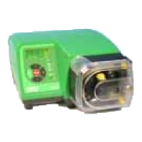
The analogue process signal must be applied to the i/p ter-
minal of the Analogue 1 connector (J5). Ground to the 0V
terminal of the same connector. The pump will provide an
increasing flow rate for a rising control signal (non-inverted
response) or an increasing flow rate for a falling control sig-
nal (inverted response). See 16.2 Analogue in the Setup
menu.
4-20mA circuit impedance: 250Ω.
For voltage mode, 0-10V, a stable, reliable voltage source can be used with a DC
voltmeter. Circuit impedance: 22kΩ.
Inverting the response is set up in software. Do not invert the polarity of the termi-
nals.
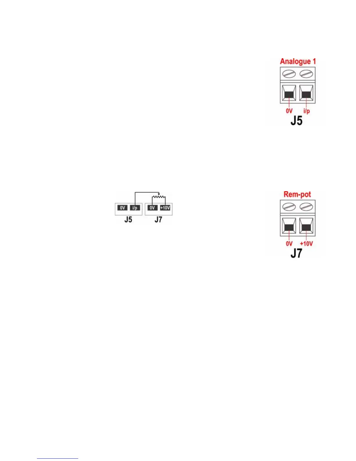
A remote potentiometer with a
nominal value of between 1k and
2k with a minimum of 0.25W
should be wired between the ter-
minals of the Rem-pot connector
(J7) and the i/p terminal of the
Analogue 1 connector (J5). When
using a remote potentiometer, do not apply a voltage or cur-
rent control input signal at the same time. The speed control
signal will require calibration relative to the minimum and
maximum settings of the potentiometer. This is done in soft-
ware - see 18.1 Trim in the Setup section.
When using a remote potentiometer, it is important to set the analogue input to volt-
age in the Setup menu. Otherwise the reference voltage supply from the Rem-pot
connector will be overloaded and will not provide a full 10V.