A. All needle valves must be closed on test kit.
B. Open test cock No. 4 and ush test cocks Nos. 1, 2 and 3 on reduced pressure
assembly then close test cock No. 4.
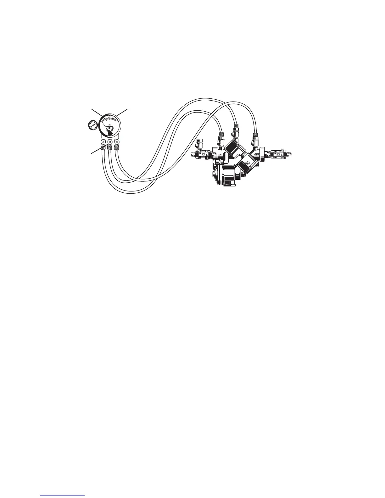
C. Attach hoses as shown. Bleed air from kit, close No. 2 shutoff.
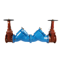
909QT shown
No. 2 shutoff
Bleed Valve A
Bleed Valve B
High
(red)
Bypass
(yellow)
Low
(blue)
Test No. 1 - Check Valve No.2
Purpose: To test check valve No. 2 for tightness against
reverse ow.
Requirements: Valve must be tight against reverse ow under
all pressure differentials.
Step 1 Slowly open the needle valve “A” high side (red) and “C”
bypass (yellow). Keep the “B” low (blue) closed.
Step 2 Open test cock No. 4.
Step 3 Indicated pressure differential will decrease slightly. If
pressure differential continues to decrease (until the vent
opens) the No. 2 check valve is reported as “leaking”.
Test No. 2 - Shutoff Valve No. 2
Purpose: To test shutoff valve No. 2 for tightness.
Step 1 After passing Test No. 1, continue to test No. 2 by
closing test cock No. 2.
Step 2 The indicated pressure differential will decrease slightly.
If pressure differential continues to decrease
(approaching “zero”), the No. 2 shutoff valve is reported
to be “leaking”. Note: A leaking No. 2 shutoff will give a
false reading in tests No. 3 and 4.
Test No. 3 - To Test No. 1 Check Valve
Purpose: To test check valve No. 1 for tightness.
Requirements: Valve must be tight against reverse ow under
all pressure differentials.
Step 1 Close needle valve “A” high side (red) and open test
cock No. 2
Step 2 Close test cock No. 4. Disconnect bypass hose (yellow)
at test cock No. 4.
Step 3 Open needle valve “B” low (blue) and “C” bypass
(yellow), bleeding to atmosphere, then closing needle
valve “B” (blue) restores the system to a normal
static condition.
Step 4 Observe the pressure differential gauge. If there is a
decrease in the indicated value, the No. 1 check valve is
reported as “leaking”.
Test No. 4 - Pressure Differential Relief Valve
Purpose: To test operation of pressure differential
relief valve.
Requirements: The pressure differential relief valve must
operate to maintain the “zone” between the two check valves
at least 2psi less than the supply pressure.
Step 1 Close needle valve “C” bypass (yellow).
Step 2 Open needle valve “A” high side (red).
Step 3 Open needle valve “B” low (blue) very slowly until the
differential gauge needle starts to drop.
Step 4 Hold the valve at this position and observe the gauge
reading at the moment the rst discharge is noted from
the relief valve. Record this as the opening differential
pressure of the relief valve. Note: it is important that the
differential gauge needle drops slowly.
Step 5 Close test cocks Nos. 2 and 3. Remove hose from test
cocks Nos. 2 and 3.
Step 6 Use bypass hose (yellow) to relieve pressure from test
kit by opening needle valve “A”, “B” and “C” and bleed
valves “A” and “B”.
Step 7 Remove all test equipment and open No. 2 shutoff valve
of the device.
4
CAUTION: To prevent freezing, hold Test Kit vertically to drain differential gauge and hoses prior to placing in case.
For additional testing information, send for IS-TK-DP/DL, IS-TK-9A, IS-TK-99E or IS-TK-99D.
Test Procedure for Reduced Pressure Assembly

 Loading...