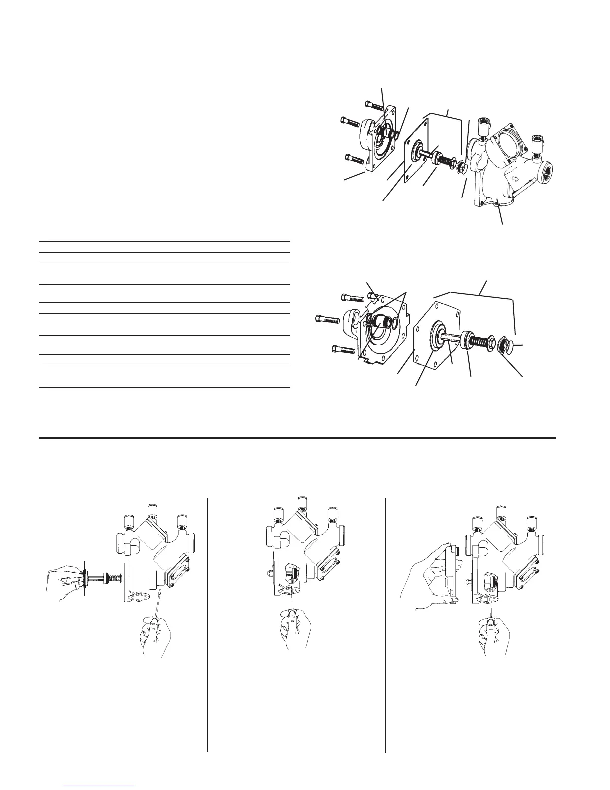
1. Remove the four bolts that hold the relief valve cover
in place.
2. Remove the cover. The stainless steel adapter, with o-ring
attached will be free to be removed simultaneous with the
removal of the cover. Pull out the relief valve assembly.
Note: the spring tension in the relief valve assembly is
contained in the design of the relief valve; therefore, the
relief can be removed in a one-piece spool-type assembly.
3. The relief valve seat and disc may be cleaned without
disassembly of the relief valve assembly. If it is determined
that the relief valve diaphragm and/or disc should be
replaced, the relief valve module can be readily
disassembled without the use of special tools.
Repair Kits
†
Relief Valve Kits
Order Code No. Kit No. Size in. mm
0887126 RK 909 VT
3
⁄4 – 1 20-25
0887138 RK 909 VT 1
1
⁄4 – 2 32-50
Kit includes: Relief valve assembly, Seat, Seat o-ring, Cover o-ring
and lubricant.
Rubber Parts for Relief Valve
0887131 RK 909 RV
3
⁄4 – 1 20-25
0887141 RK 909 RV 1
1
⁄4 – 2 32-50
Kit includes: Diaphragm, Disc assembly, Seat o-ring, RV o-ring,
Piston o-rings, Cover o-ring and lubricant.
Seat Kits for Relief Valve
0887372 RK 909 SV
3
⁄4 – 1 20-25
0887371 RK 909 SV 1
1
⁄4 – 2 32-50
Kit includes: Seat, Seat o-ring, Piston o-ring and lubricant.
†
Note: 1
1
⁄4" - 2" (32-50mm) 909/909M1 share a common kit.
To Prevent Shaft Damage Assemble As Shown:
Caution: If cover will not press against body, assembly is crooked and tightening bolts will bend shaft. Do not force the cover into
place as damage may result from misalignment.
Figure 1
Figure 2
Figure 3
Figure 1:
To assemble the Relief Valve Assembly
have a screwdriver ready.
Figure 2:
Depress the Relief Valve Assembly,
carefully guiding it against the two pound
spring load. When properly aligned, the
piston is in the cylinder bore. Insert the
screwdriver as shown.
Figure 3:
The Relief Valve Assembly is held
encapsulated by the screwdriver. You
should now have both hands free to
bolt down the cover. Insert and snug
two bolts 180° apart to hold the cover.
Finish inserting the remaining bolts and
snug up evenly, alternating until secure.
Remove the screwdriver.
Disc Assembly
Piston
O-ring
Relief Valve
Assembly
RV O-Ring
Stem
Seat
Body
Cover
Diaphragm
Piston
6
Cover
Seat
O-ring
Size
3
⁄4” – 1”
Disc Assembly
(2) Piston
O-rings
Relief Valve
Assembly
(2) RV O-Rings
Stem
Seat
Diaphragm
Piston
Seat
O-ring
Size 1
1
⁄4" – 2" (32-50mm)
For further details contact your local technical sales
representative, see back page.
Servicing the Relief Valve
3
/4" to 2"

 Loading...