Benchmark 750-3000 Boiler Installation & Startup Manual
SECTION 2 – INSTALLATION
OMM-0121_D • GF-205 • 5/9/2019 Technical Support • (800) 526-0288 • Mon-Fri, 8 am - 5 pm EST Page 35 of 122
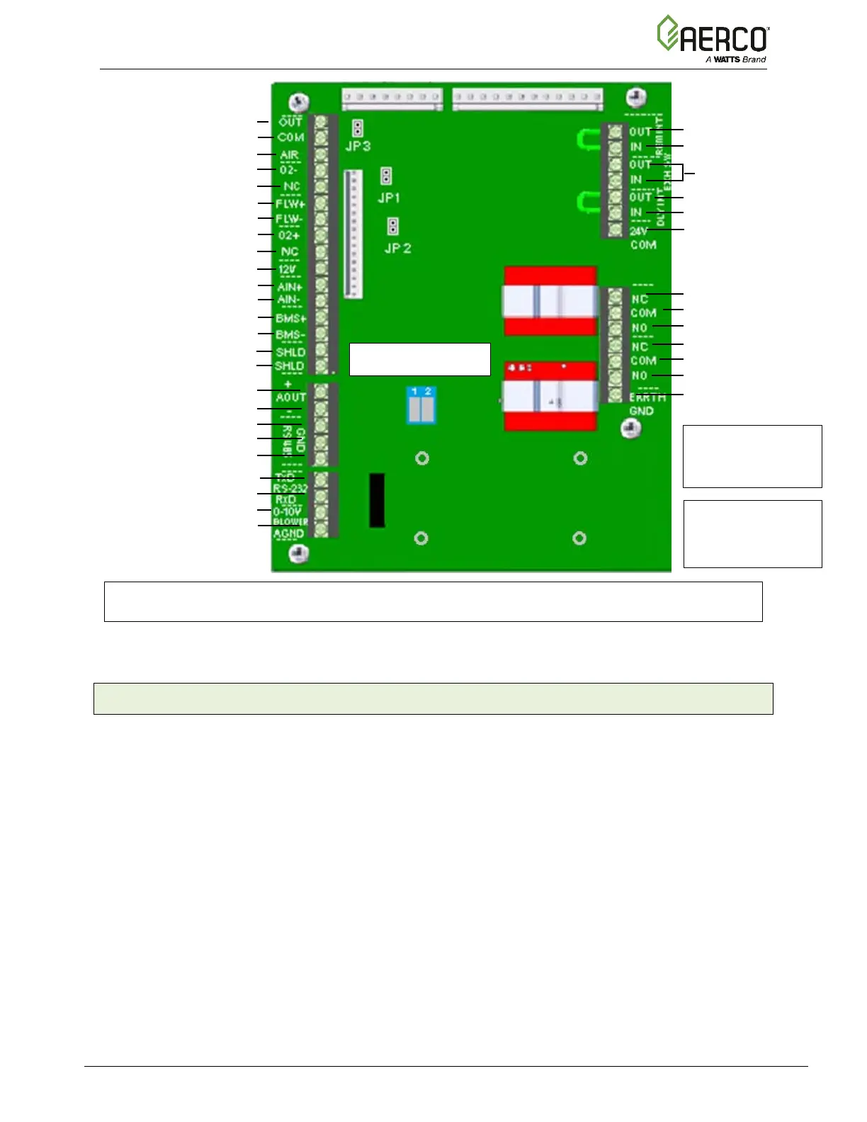
Outdoor Air
Air Sensor Common
Air Temp Sensor
O2 Sensor –
Not Used
Spark Signal +
Spark Signal –
O2 Sensor +
Not Used
+12 V Out
Analog In +
Analog In –
Valve Feedback +
Valve Feedback –
Shield
Shield
Analog Out +
Analog Out –
RS-485 +
RS-485 Ground
RS-485 -
RS-232 - TxD
RS-232 - RxD
VFD/Blower +
VFD/Blower –
Remote Intl’k OUT
Remote Intl’k IN
NOT USED
Delayed Intl’k OUT
Delayed Intl’k IN
Not Used
Fault Relay N.C.
Fault Relay COMM
Fault Relay N.O.
Aux Relay N.C.
Aux Relay COMM
Aux Relay N.O.
Not Used
NOTE:
Refer to this image for connections rather than the silkscreen labels shown on the board.
Figure 2-11: I/O Box Terminal Strips
2.11.1 Outdoor Air & Air Sensor Common
An outdoor temperature sensor (P/N 61047) is required for the INDOOR/OUTDOOR RESET
mode of operation. It can also be used with another mode if it is desired to use the outdoor
sensor enable/disable feature, which allows the boiler to be enabled or disabled based on the
outdoor air temperature.
The factory default for the outdoor sensor is DISABLED. To enable the sensor and/or select an
enable/disable outdoor temperature, see Section 2.6: CONFIGURATION Menu, item 7, in the
Benchmark 750 – 3000 Operation and Maintenance Guide, OMM-0122 (GF-206).
The outdoor sensor may be wired up to 200 feet (61m) from the boiler. It is connected to the
OUTDOOR AIR and AIR SENSOR COMMON terminals of the I/O board (Figure 2-11). Wire the
sensor using a twisted shielded pair wire from 18 to 22 AWG. There is no polarity to observe
when terminating these wires. The shield is to be connected only to the terminals labeled
SHIELD in the I/O Box PCB. The sensor end of the shield must be left free and ungrounded.
When mounting the sensor, it must be located on the North side of the building where an
average outside air temperature is expected. The sensor must be shielded from direct sunlight
as well as impingement by the elements. If a shield is used, it must allow for free air circulation.
120 VAC, 30 VDC
5 Amps, Resistive
120 VAC USED
DIP 1 Modbus Term
DIP 2 RS232 Enable

 Loading...


