10 of 48
Equipment Wiring
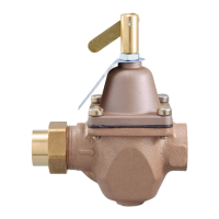
Wiring the Analog Mixing Output
----------------------------------------------------------------------- -----------------------------------------------------------------------
The control can operate a mixing valve by providing a 0-10 V (dc) or a 4-20
mA signal to the valve actuating motor.
• If applicable, connect the mixing actuator positive (+) to terminal 1.
• If applicable, connect the mixing actuator negative (-) to terminal 2.
The control provides a floating action signal to operate a floating action actuator. The
floating action mixing output uses dry relay contacts that can switch either 24, 120, or
230 V (ac). When using 24 V (ac), a Transformer 009 is required to power the actuator.
The actuator terminals are typically labeled for clockwise and counterclockwise rotation.
The control's open and close terminals are wired to the actuator depending on the
direction the valve rotates to open and close respectively.
• Connect the power source to the Pwr terminal 4 on the control.
• Connect the Opn terminal 3 to the actuator terminal that rotates the valve open.
• Connect the Cls terminal 5 to the actuator terminal that rotates the valve close.
• If using a 24 V (ac) transformer, connect the actuator common to the transformer C.
• If using a 120 V or 230 V (ac) power supply, connect the actuator common to the
power supply neutral (N).
Wiring the Floating Action Mixing Output
--------------------------------------------------------------- ---------------------------------------------------------------
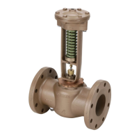
A variable speed injection mixing pump requiring up to 230 V (ac), 2.4 A is
operated through terminals 3 and 4. For simplicity in wiring and troubleshooting,
a separate breaker for the pump is recommended.
• Connect 115 or 230 V (ac) power L to the Pwr Mix terminal 4.
• Connect a wire from Var terminal 3 to the pump L.
• Connect a wire from the pump N to the power Neutral.
• Connect the ground wire (G) to the pump.
Wiring the Injection Mixing Pump
---------------------------------------------------------------------- ----------------------------------------------------------------------
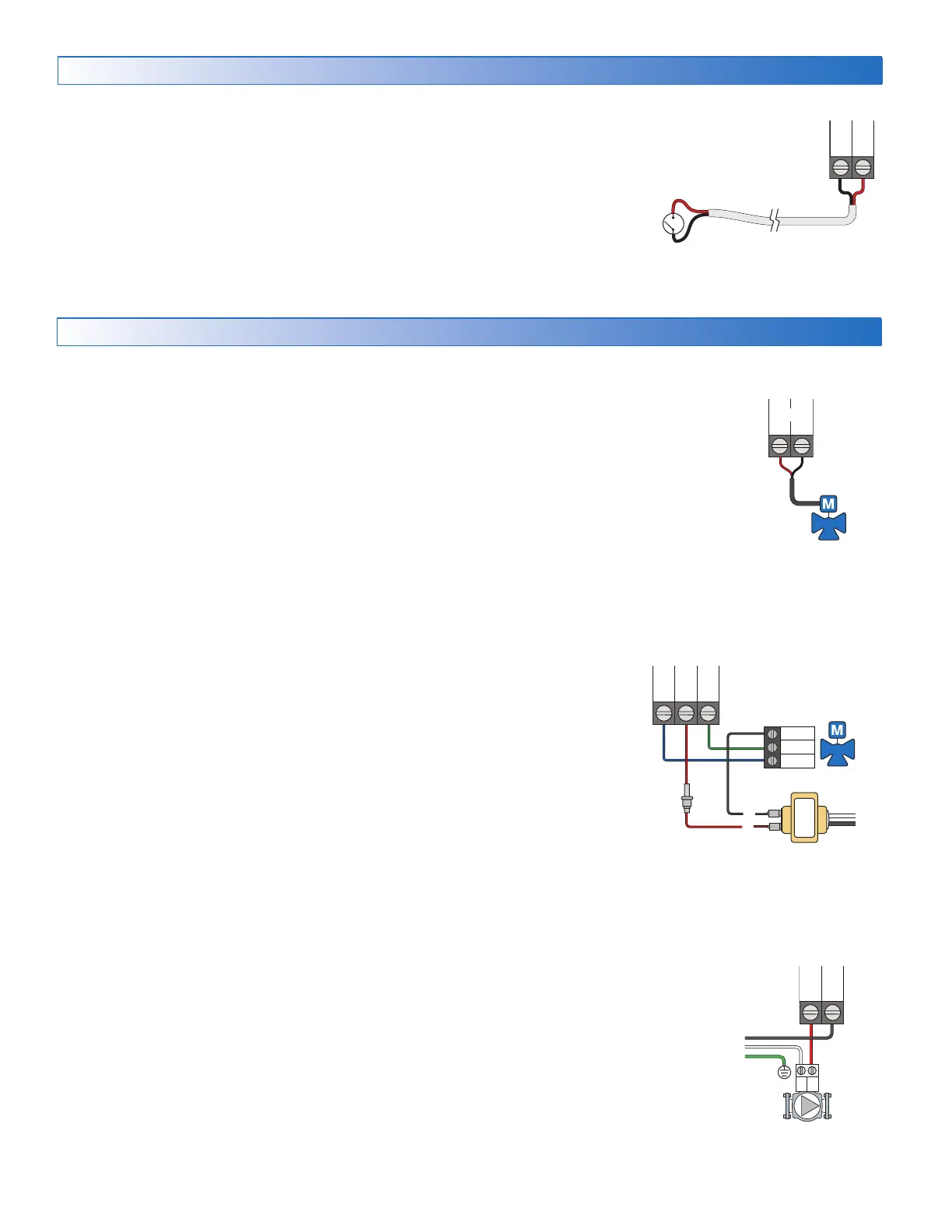
Manual Melt Input
The manual melt input allows the control to be manually switched to melting
operation using a switch. This connection is optional.
If the Manual Melt input is used:
Connect a switch to terminals 13 and 14. The switch may be either dry (no voltage)
or a voltage signal up to 32 V (ac).
Man
Com
Mix V/mA
Com
Close
Open
C
N
L
R
Opn
Pwr
Cls
L
NG
Opn
Var
Pwr
Mix
 Loading...

![Preview: Watts AERCO Edge [ii]](https://data.easymanua.ls/products/808371/200x200/watts-aerco-edge-ii.webp)