12 of 48
Provide a 15 A circuit for the input power.
• Connect the 115 V (ac) line wire (L) to terminal 29.
• Connect the neutral wire (N) to terminal 30.
N
L
Power
Wiring the Input Power
--------------------------------------------------------------------------------- ---------------------------------------------------------------------------------
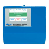
If the heat relay is operating a pump:
The pump can be rated up to 230 V (ac), 5 A, 1/3 hp and switched through
terminals 25 and 26. For simplicity in wiring and troubleshooting, a separate
breaker for each pump is recommended.
• Connect the power source line wire (L) to terminal 26.
• Connect a wire from terminal 25 to the pump L.
• Connect a wire from the pump N back to the power source neutral.
• Connect the ground wire (G) to the pump.
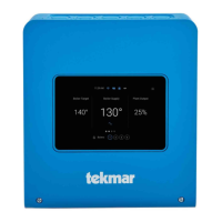
If the heat relay is wired to an electrical contactor:
• Connect a wire from terminal 25 to the electrical contactor R.
• Connect a wire from terminal 26 to the electrical contactor C.
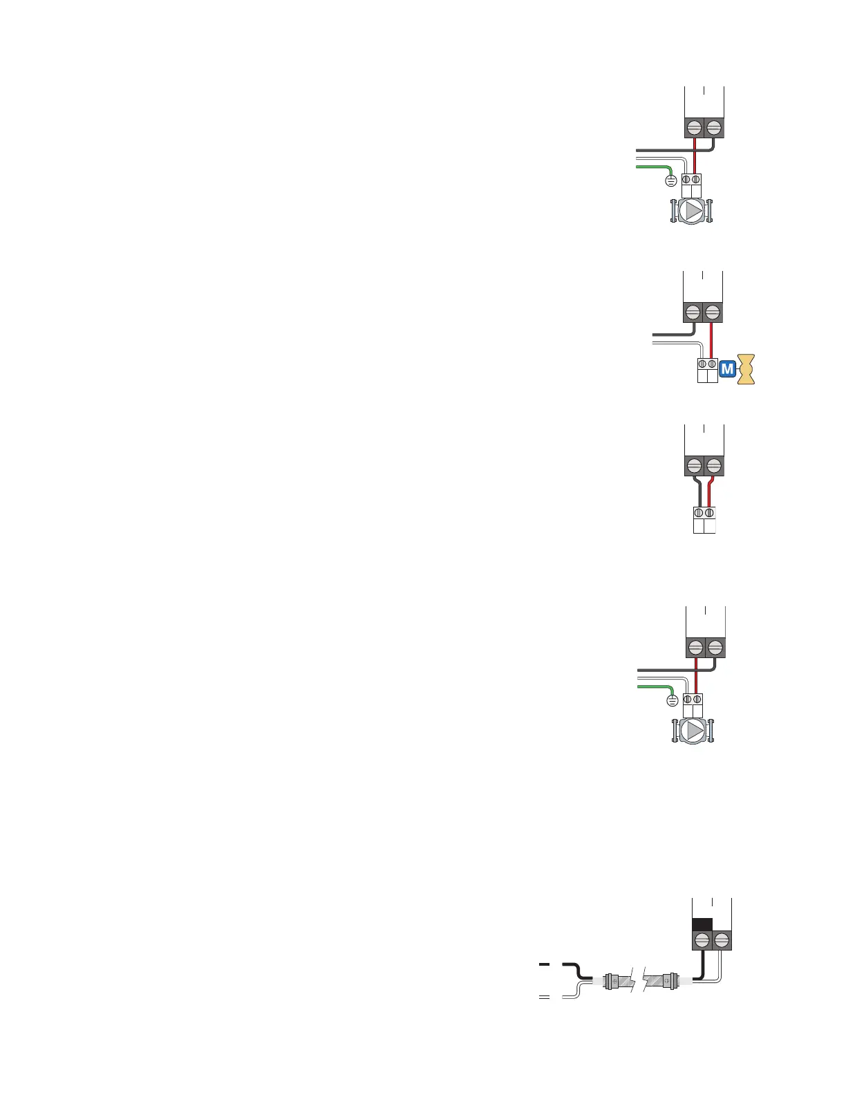
If the heat relay is wired to a 24 V(ac) on-off valve:
• Connect the power source red wire (R) to terminal 25.
• Connect a wire from terminal 26 to the valve R.
• Connect a wire from the valve C to the power source common.
Wiring the Heat Relay
---------------------------------------------------------------------------------- ----------------------------------------------------------------------------------
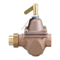
A system pump requiring up to
230 V (ac), 5 A, 1/3 hp
can be switched through
terminals 27 and 28. For simplicity in wiring and troubleshooting, a separate
breaker for each pump is recommended.
• Connect the power source line wire (L) to terminal 28.
• Connect a wire from terminal 27 to the pump L.
• Connect a wire from the pump N back to the power source neutral.
• Connect the ground wire (G) to the pump.
Wiring the System Pump
------------------------------------------------------------------------------- -------------------------------------------------------------------------------
L
N
G
L
NG
Heat
RC
Heat
Relay
Heat
Relay
L
N
G
L
NG
System
 Loading...
![Preview: Watts AERCO Edge [ii]](https://data.easymanua.ls/products/808371/200x200/watts-aerco-edge-ii.webp)