SECTION
INSTALLATION
ANO
OPERATION
2.1
MECHANICAL
INSTALLATION
After
unpacking
the
instrument, visuaiiy inspect ali external
parts
for possible
damage to knobs,
connectors,
surface
areas,
etc. If damage is
discovered, file a
claim
with the
carrier
who transported
the unit. The
shipping container
and packing
material
should be saved in case
reshipment
is required.
NOTICE
Unless otherwise
specified at the time of pur-
chase, all Wavetek
instruments are shipped from
the factory with the
power
transformer con-
nected
for
operation on a
nominal
115-volt ac
line supply, and a 'k
amp 115 V line fuse.
No
mechanical
installation is
required when the
instrument
is
to
be used as a
portable bench top
instrument.
If
a
rack-mounting
configuration, or
a
Rack
Adapter Kit
(see
paragraph
1.4),
is
provided, the unit may
be mounted in a
standard
19-inch equipment rack. Instructions
for attaching
the Rack Adapter Kit are
provided
with the kit.
2.2
ELECTRICAL
INSTALLATION
2.2.1 Power
Connection
Connect
the ac line
cord to
the mating connector at the
rear
of the unit.
NOTICE
Conversion
for 230-volt
operation requires resetting a
switch at the rear of the instrument. To reset
the
115/230
conversion
switch (concealed
by
the
rear panel) remove the
rear
panel,
set
the slide switch to
230,
and
replace the
panel.
Install
a fuse
with
a
rating of
1/8
amp at 230
volts.
2.2.2
Signal Connections
Use
50f2
shielded cables equipped with
female BNC con-
nectors
to
distribute all RF
signals when
connecting this
instrument
to
associated
equipment.
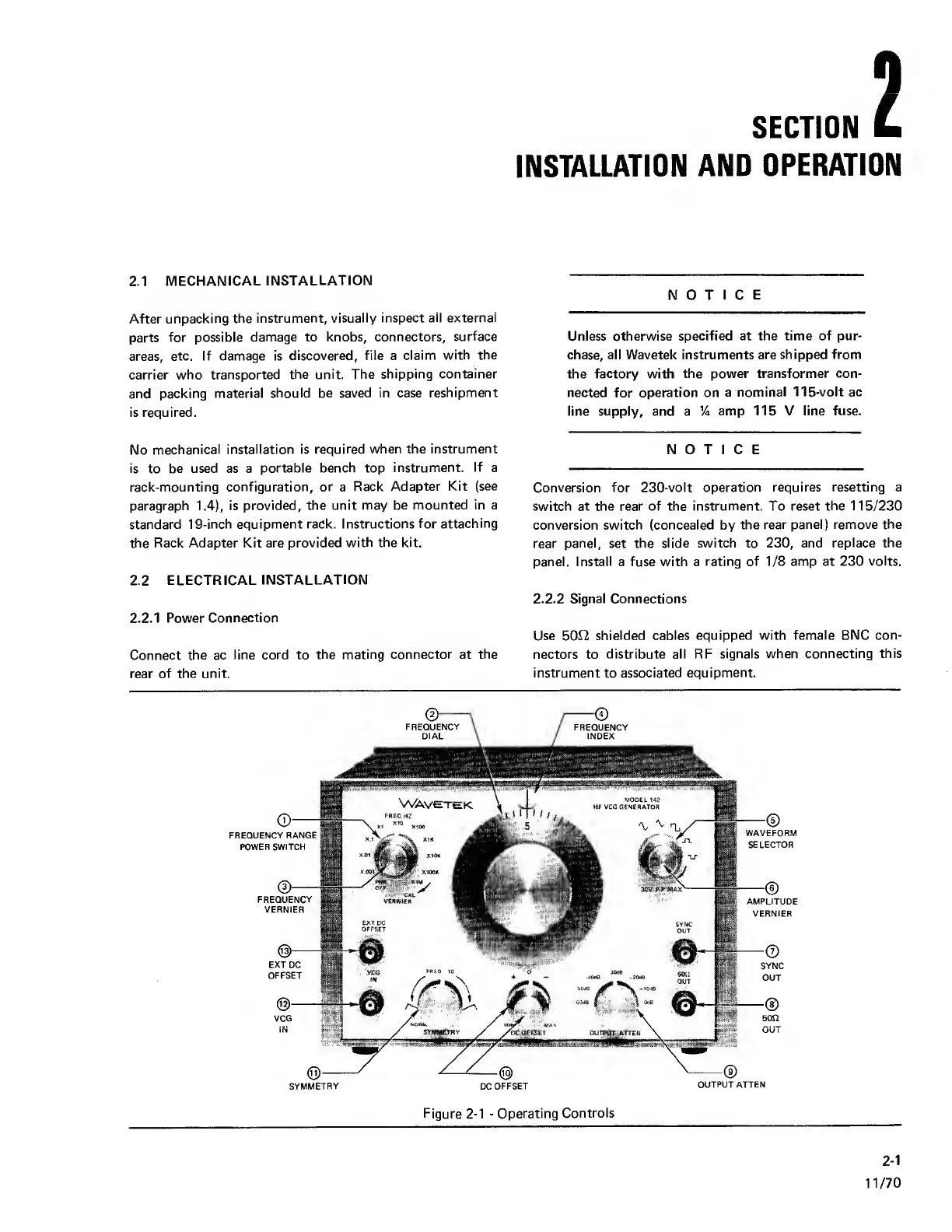
VERiMiEfl
EXT
DC
OFFSET
FREQUENCY
FREQUENCY
WAVEFORM
SELECTOR
AMPLITUDE
VERNIER
DC
OFFSET
OUTPUT
ATTEN
EXT DC
OFFSET
VCG
IN
FREQUENCY RANGE
POWER SWITCH
®
—
FREQUENCY
VERNIER
SYMMETRY
Figure
2-1
-
Operating
Controls
2-1
11/70