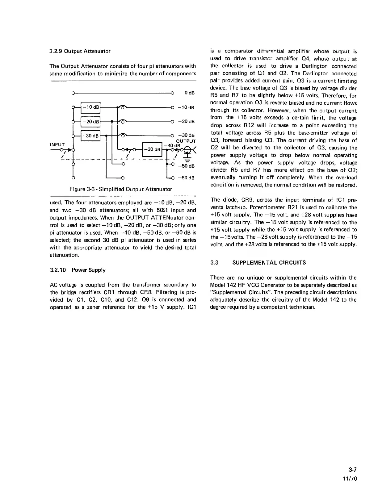
3.2.9 Output Attenuator
The Output Attenuator consists
of
four pi
attenuators with
some
modification
to
minimize the number of components
0
0
OdB
Figure
3-6
-
Simplified
Output
Attenuator
used. The
four
attenuators employed
are —lOdB,
—
20dB,
and two
—30
dB attenuators; all with 500 input and
output impedances. When the OUTPUT ATTENuator con-
trol is used to select
—
10
dB,
—20
dB, or
—30
dB;
only
one
pi attenuator is
used.
When
—40
dB,
—50
dB, or
—60
dB is
selected; the second
30
dB pi attenuator is used in series
with the
appropriate attenuator to yield the desired total
attenuation.
3.2.10 Power Supply
AC
voltage
is
coupled from the
transformer secondary to
the bridge rectifiers CR1
through CR8.
Filtering
is
pro-
vided by Cl, C2, CIO,
and Cl
2.
Q9
is connected and
operated as a
zener reference
for the
-i-15
V supply. IC1
is a comparator difte-ential
amplifier whose
output
is
used to drive
transistor amplifier
Q4,
whose
output
at
the collector
is
used to
drive a Darlington
connected
pair consisting of Q1
and Q2. The
Darlington
connected
pair provides
added current
gain; Q3 is
a current
limiting
device.
The base voltage of
Q3
is biased
by voltage
divider
R5
and
R7
to be slightly
below -M5
volts.
Therefore,
for
normal
operation Q3 is
reverse
biased
and no current
flows
through
its
collector.
However,
when the
output current
from
the -H5
volts
exceeds
a certain limit,
the
voltage
drop
across
R12 will increase to a point
exceeding the
total voltage
across
R5 plus
the base-emitter voltage of
Q3,
forward
biasing Q3. The
current driving the
base of
Q2 will be diverted to the collector
of
Q3,
causing the
power supply voltage to drop below normal
operating
voltage.
As the power supply
voltage drops, voltage
divider R5 and
R7
has
more effect
on the
base
of
Q2;
eventually
turning it off completely.
When the
overload
condition is removed,
the normal condition will
be restored.
The
diode, CR9,
across the input terminals
of IC1 pre-
vents latch-up.
Potentiometer R21 is
used to calibrate
the
-1-15
volt
supply. The
—15
volt, and
+28
volt supplies
have
similar circuitry.
The
—15
volt supply is
referenced
to
the
+15
volt
supply
while the
+15 volt supply is referenced
to
the
—15
volts. The
—28
volt supply is referenced
to
the
—15
volts, and
the
+28 volts is referenced to
the +15 volt
supply.
3.3 SUPPLEMENTAL
CIRCUITS
There
are no unique or
supplemental
circuits within the
Model
142 HF VCG Generator to be
separately
described as
"Supplemental
Circuits".
The preceding circuit descriptions
adequately describe the circuitry of the Model 142
to
the
degree required
by a
competent technician.
3-7
11/70